SilverMAX Colloidal Silver Generator
There are quite a few skeptics as to the benefits of Colloidal Silver, I for one can neither promote nor discount the benefit of it’s use as I have very little experience with it myself. My Mother In-Law showed an interest in producing colloidal silver at home which seemed like the perfect opportunity for me to help her out, and also to produce a device that potentially could help many others attain a high end generator for home production at a low cost in comparison to other commercial generators available on the market today.
Project Videos:
Project Blog Posts:
Project Photos:

If you do decide to download the project, by all means take the time to read through the README.txt file. I’ve put quite a bit of information in there and it will be a good starting point if you are seriously considering building this project. Feel free to also contact me here if you have any questions, etc…
Features:
- Constant Current Generator ( more consistently sized silver ions )
- Automatic Polarity Reversal ( virtually no build up of negatively charged particles on one electrode )
- Variable Speed Magnetic Stirrer
- Adjustment Knob for the desired production level / speed
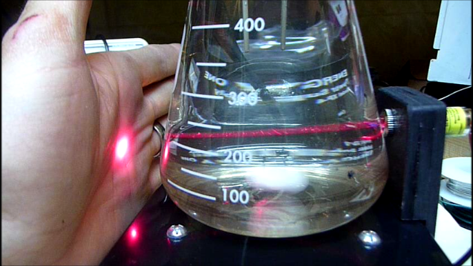
- Built-In Laser for visually checking silver particle density
Software Requirements:
- EAGLE 6.4 Free / Lite version
- MPLABX with Free XC8 Compiler
Hardware Requirements:
- Soldering Skills
- PCB Making Skills ( toner transfer )
- PICKIT2 ( or PICKIT3 ) Programmer
What’s included:
- EAGLE schematics & board layouts for:
- Controller & Interface
- Enclosure Fan Mounting Holes
- Laser Mount Holes
- PIC12F510 XC8 Source Code
- Parts List
- Instruction Manual
- README.txt – Lots Of Good Info
License:

This work is licensed under a Creative Commons Attribution-NonCommercial-ShareAlike 3.0 Unported License.
Download the Project:
Current Version: 1.0a

SilverMAX Colloidal Silver Generator Project Files
SilverMAX_Colloidal_Silver_Generator_1.0b.zip
Version: 1.0b
SilverMAX_Colloidal_Silver_Generator_1.0b.zip
Version: 1.0b
Changelog:
12/28/2014 – version 1.0b
Correction made to the Parts_List.xls & .csv files. R15 listed with the 10k potentiometers, though it is actually a 1/4 Watt 10k wirewound resistor. Fixed in this update…
Correction made to the Parts_List.xls & .csv files. R15 listed with the 10k potentiometers, though it is actually a 1/4 Watt 10k wirewound resistor. Fixed in this update…
4/27/2014 – version 1.0a
initial version uploaded…
initial version uploaded…
Hi
First of all I would like to thanks a lot for share your SilverMAX Colloidal Silver Generator. Your project and completion of the work is the best for me. I checked many projects in internet. It is exactly what I am looking for.
I want to start build my generator as soon as possible … means when I’ll buy all parts.
I am not experienced with build projects like your SilverMAX Colloidal Silver Generator, but I want to try.
I have a few questions if is not problem for you..
1. Does your device is constant current ?
2. Do you know what size silver particles in your collodial silver liquid are ? I know it is dificult to say because recuired expensive equipment.
3. How to program ?
I have acces to Pickit 2 (my friend has in job), but I do not know how.
SilverMAX Colloidal Silver Generator has any special socket or pins designed for it ?
Kind Regards from Poland
Piotr
Hey Piotr,
No problem on posting the project.
To your questions:
1. The generator does operate at a constant current, which is based on a adjustment knob. It uses a buck converter to maintain the constant current as the resistance drops in the solution ( as the silver content in the solution goes up, resistance will go down ).
2. I don’t know specifically what size the particles are, though they appear to be extremely small ( the liquid is clear at 20ppm, though you will see a faint beam of light if you shine a laser through the solution at that level ). I’d imagine the particle size is quite small with that being said, however some have suggested that running a device like this with a current in the microamps is required for extremely small ( nano sized ) particles – this is possible though you would have to adjust some of the components ( mainly the Rsense resistor, possibly the comparator, and the knob’s resistance value, etc… ).
3. You mentioned you have access to a PICKit2, your friend should know how to program the PIC with that. Make sure you get the same PIC as listed in the materials list, and then you can simply download the included .hex firmware file to the PIC using your friend’s PICkit 2. That is probably the easiest part of the project, the real meat and potatoes comes from all the other work etching the boards, soldering the components, etc…
Definitely keep me posted with your progress,
Cheers,
Morgan
Wow! Great job Morgan, I to have equipment/shop to make stuff, but all the work and cost of your project discourages me to try. I’m disabled with chronic lyme disease 24 years and haven’t the heart to do all the work. Wonderful job thought, you work like a real pro!!! I do think silver works, a friend gave me a 2oz dropper bottle of Colloidal Silver and I’ve notice my back pain & stomach pain reduced. I have also notice some reduction in rheumatoid arthritis has reduced enough that I can have some sweets which normally would seriously aggravates it. Maybe some time in the future I will have a way to make it myself. Your project came out looking more professional than the super expensive SilverLungs Colloidal Silver Generator, good job!!!
Jerry
Hi, really nice work, and better than the SilverLungs generator.
Can you tell me what the actual output voltage is on the electrodes?
You use 12 volts on the power supply, with a 5 volt regulator, but doesn’t show what voltage the silver electrodes will have when it’s operational, from the constant-current regulator. What’s the output current range used, on this device?
If you had the choice, what p-channel MOSFET would you have used if you wanted to replace the ‘over-kill’ one you had on-hand.
(What’s the smallest Amp rating I can use for the part?)
Hey Marty,
Thanks for the comment, and props, it’s appreciated for sure.
The generator has a 5 volt regulator for the microcontroller and it’s components. The voltage across the electrodes is variable, as this is a constant current generator, however it does have a maximum threshold of 12 volts as currently setup in the design – you could power it with 24 volts if you wanted to, though you would need to make some adjustments, ie: since the DC fan used for the magnetic stirrer is 12VDC you would need to add in an additional 12V regulator and have it’s output go to the stirrer, etc…
As designed I have a 100 ohm current sensing resistor in series with the silver electrodes, which can be adjusted ( along with the SETPOINT_OUT potentiometer ) to get the desired current range for your own generator.
With the current design, the SETPOINT_OUT potentiometer R11 is a 10k, and is in series with a 47k resistor. It is powered by 5V DC, and will give you a range on the adjustment knob from 0V to 1V. This SETPOINT voltage is compared to the voltage across the Current Sensing resistor via the Comparator IC3, which will send either a high or low to the microcontroller indicating if adjustment is required ( the generator drives a Buck Converter via PWM, so basically the duty cycle is being adjusted to attain the desired current through RSENSE ).
At any rate, with that being said you are looking at a maximum of 1V on RSENSE which would indicate a 10mA current, or down to 0V which would of course indicate no current, but practically speaking if you can trim the knob down such that the output of the SETPOINT potentiometer is say 1mV output, you would have 10uA current through the electrodes.
Some people will talk about constant voltage / constant current, though there is no such thing, you can’t have both – so as the resistance in the solution goes down, you will end up having to reduce voltage to maintain the desired current, and that is how this system works basically.
For the MOSFET, you can probably get the smallest one you can find, you really only need one that can handle 100mA ( or even less ). I just used what I had on hand. One other thing you want to ensure is that your gate capacitance is low, and it has decent switching capabilities ( time wise ).
Cheers,
Morgan
Hi Morgan,
I truly appreciate your detailed reply.
I’m guessing this is why it takes around 5 hours to create the finished batch of ionic silver, it’s less than 1 mA at around 12 volts DC.
This is better than creating it too fast, like the other ‘retail’ devices do it, with 27 to 48 vdc, at 5 to 30 mA.
I agree with your logic, slower time frame, with lower current and voltage will create smaller ‘particles’.
This, along with my ultra-pure 99.999% (.99999) rods should create some very clean and safe ionic silver. (With steam distilled water, of course )
)
Oh…one clarification to my second posted question.
I was asking if you could match (equate) the pin-nomenclature of my programmers pin-out to the 5 pins on your device, so I don’t connect them wrongly.
Thanks a bunch for this design.
I was able to spend the larger costs on the higher-grade silver rods, rather than the electronics the other retailers over-charge for.
No problem on the quick reply. Thanks for the clarity on the second question, I think I provided a response that gives you the information you need though, look at the PICKIT pin # = Willem Pin # lines to see what I mean there – in the Generator’s schematic on the PICKIT header the pins are numbered which is what I’m referring to by PICKIT pin # …
Yes, slower is better. The device also has polarity reversing capability such that the electrodes stay much cleaner ( if this didn’t happen negatively charged particles would build up on one of the electrodes ), which results in a cleaner solution by the end of it. The stirrer is also quite nice, though I would recommend running the stirrer at it’s lowest speed ( where it is still spinning ). I find it helps prevent things from settling, and it most likely also keeps the particles much more consistent throughout the solution.
Definitely keep me posted with your progress.
Cheers,
Morgan
Hi again,
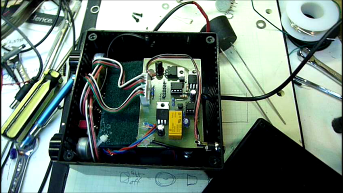
I noticed R11 and R13 are placed on the main board as small trim-pots, shown on the PDF’s in the zip file, but in the photos from the finished device, the trim-pots are not showing on the main board.
Instead, you use larger linear tapers mounted on the enclosure, (Left and right potentiometers) and connect them via the wire sets.
Was there an update that wasn’t reflected in the PDF files included in the downloadable zip file?
Oops, … I just realized, the interface board has the trim-pots, R11 and R13 (not the main board) and you’re also using the larger linear taper potentiometers on the enclosure.
Is this to get a finer adjustment from the left and right potentiometers range by adjusting the trim-pots on the interface board to ‘center’ the final range of the potentiometers?
Sorry, … I was confused before with my other post, stating I didn’t see the trim-pots on the main board.
You can delete that confused post if you want to.
Ha ha..!
Hey Marty,
There are only two potentiometers in the generator, you don’t have to build the device as I have, and thus the trim-pot part is used on the board to show that a potentiometer should be used there – either as a trim-pot on the board ( if you weren’t going to use an enclosure ), or if you have an enclosure as a linear taper pot that can be mounted to the enclosure. For my build I simply soldered wires to the trim-pot part’s through holes and then to the linear pots – those are easily mounted to the enclosure, etc.. I probably should have been more specific about that in the documentation. I would also recommend something that will give a linear response, versus audio taper, as the position of the knob will better reflect the results you attain, etc…
Let me know if you have any other questions,
Cheers,
Morgan
Thanks for clarifying that potentiometer confusion for me.
Although I noticed you had wires connected to those trim-pot holes on the interface board, to your enclosure mounted parts, when I looked thru more of the photos later-on, but wanted to wait for your answer before I posted again saying I think I understand, in case I was wrong.
I’ve decided to use as many SMD parts as I can find, to shrink the boards, into being able to put everything on one board, using a two-sided board design.
The interface section will be the front side, and the main board section will be the back-side with as many SMD parts as possible so I don’t need to drill too many holes to connect the both sides to each-other, or need so many cables.
I’ve had good results making double sided boards in the past, matching-up both sides connections, using a photo etching method, and my ink-jet printer, with transparency film.
(I don’t have a laser printer)
I’ll post the parts choices, links, when I have all of them sorted out, for you to verify if my choices are correct.
I also found a smaller amp and voltage SMD P-channel MOSFET, and a 5volt DPDT latching relay in SMD as well.
I hope all my fancy etching and developer chemicals are still good, and I can find my board and transparency mounting jig for the ultraviolet lamp to expose the developer with.
Oh well…time to look for that too before buying all the other parts.
It’s been almost 10 years since I made my last photo-etched double-sided PCB. Should be fun times again. Ha ha.
Hey Marty,
Very cool on going double sided with as much SMD as you can, definitely the way to go if you want to put it in a really small enclosure. With the enclosure I used the size wasn’t an issue as the enclosure needed to be at least 80mm x 80mm to accommodate the fan for the stirrer.
Cheers,
Morgan
Hi again Morgan
This thread is getting complex, will it all fit on your blog?
Ha ha..! (Joking)
I found my chemicals, but they’re at the bottom of 6-feet of stuff piled on top of it. Plus, I can’t find my glass pressure easel that holds the artwork against the board, to expose the photo-resist on the board with the ultraviolet lamp. )
)
(I found the lamp though
I will most likely simply send the Gerber file to a board manufacturing house and have 3 or 5 sample boards made for whatever the minimum costs are.
If the chemicals are spoiled already, or I will need to remove nearly 100 pounds of clutter off of the box they’re in, it’s going to be easier, and less costly to just have some boards made professionally, after I re-do the Gerber file for SMD.
By the way…I’m not trying for SMD to just save space. I’m also trying to lessen the ‘manufacturing steps’ needed as well.
Less holes to drill means fewer plated-thru holes to make on the 2-sided board, plus lower costs for PCB creation by a board manufacturing house.
And fewer cables inside means less time to construct it. This will lower the over-all costs to make and populate the board if a kit, or finished product is made.
I may make the enclosure as large as yours too, or at least large enough for a 1000mL beaker or flask to fit.
I was also thinking about mounting the Fan/Stirrer to the bottom opening panel of the enclosure, so the top will be free of the screws that may block a fatter shorter flask/beaker from fitting flat, without being limited by the locations of the fans mounting screws on top.
I was wondering…does the free version of the Eagle PCB design software support ‘copper pour’?
If so, I can make a copper pour for the ground connections on the bottom side, and a power copper pour for the 5 volts, and 12 volt areas, on the top side. This will also not only stabilize the circuit from EMI/RFI (not that it may need it) but will also simplify the signal trace pattern.
I’m also wondering… is it possible to use that unused op amp in the comparator chip to make a continuity indicator, attached to the silver electrodes, and have the PIC monitor the conduction of the liquid?
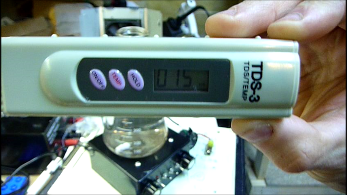
I don’t really think a PPM meter will accurately measure ions. It’s not really particles of metal being created. It’s more an Ionic Silver Generator than a colloidal generator.
But it’s good because the ion is the more active item, at least for me, what I’m looking for, and science sites said they found out the Ion is more bio-active and bio-effective than the nano-metal particle, anyway.
This last added feature is just a thought, but it would open a possibility of automatically shutting off when the circuit detects a SETPOINT of conductivity in the water.
Anyway, I’ll make a notation of the SMD parts I hope will match your suggested pin-thru parts, soon, and post the links here. Unless you’d like me to eMail them to you, to keep it private for now…
Your eMail address shows on the posted reply mailings I get when you reply here.
Cheers to you too,
Marty
Wow Morgan, I gotta remember to get more sleep.
I thought I saw the kit request and mention of someone’s Lyme Disease on the other Instructables site, ‘steps’ section, but it was in fact here on these comments, near the beginning.
Then, in my last comment before this one, I said;
‘…unused op amp in the comparator chip to make a continuity indicator,…’
Which should have had ‘conductivity’ instead of ‘continuity’.
Well, anyway, I’ve been staying up late invisioning how I want to make this enclosure, and circuit board.
Lots of fun..!
Your design is so clean and efficient.
A delight to ‘tinker’ with.
I noticed all the I/O pins are already used on the PIC12F510 so any attempt to monitor the conductivity will need to be separate from this PIC IC.
I did some Google-ing all this time, and saw this is a project of its own.
Ha ha…
There’s a schematic mentioned on …
http://www.reefcentral.com/forums/showpost.php?s=988be97e81541d1ec401729c22112ac9&p=17001272&postcount=14
And lab grade probes with Glass outer enclosure, and Platinum sensors (3rd and 4th down on that page) at…
http://www.nengshi.com/en/new_lab.asp?id=254
I guess, that’s if you want to be ‘perfectly accurate’ with a ‘set standard’ of ’0~200μs/cm’
–
I’d want glass for the outer shell, so as not to screw-up the IONS in the water.
But all this may be a MAJOR over-kill
–
Maybe just using the silver rods to measure the falling resistance that outputs a current to an indicator of some kind, and shutting down the circuit at a set-point – is easier than the Lab-grade method and is actually more of what I was thinking of.
Does the RSENSE resister give a voltage or current-out to the LM393A ?
If so, would tapping off that, for a second connection to the other section of the comparator IC, disrupt the reading on the first section to pin 3 ?
Anyway, I was hoping to make a simple analog indication of how the current or voltage is changing and display it, with a reference and set-point for activating another relay (SPST) just to act as an automatic S1 (power-switch) breaker.
But even this may be more complex than I’m thinking of.
I’m just trying to add as many features before I make the boards up, and not need to re-do it again later.
The most ‘bang’ for my bucks.
I’m even thinking of adding a trace
pattern, wired for the Willem ICSP connector, so others with that programmer need not get the PICkit2 and just need to connect the 5-pin connector to that trace pattern instead of the original PICkit trace pattern.
Yeah, I’m thinking of every little addition. That’s what’s keeping me up late… Ha ha..!
Anywho…I’m hoping you’re enjoying the holiday weekend, and having fun.
I sure am..! With this.
Speak to ya after the holiday…bye.
Hey Marty,
Someone had asked about kits, or I mentioned it as well if there was interest that I may put some out, but at this point there hasn’t been too much inquiry so I probably won’t do it. This project is also being put out there with the following license ( http://creativecommons.org/licenses/by-nc-sa/3.0/ ) for non-commercial use. If you are interested in selling kits using my design definitely let me know, possibly we can work something out on that.
The probe is an interesting idea, though I would probably say it is overkill at this point. The voltage between RSENSE and ground effectively represents the current flow through the electrodes, which also represents how ‘conductive’ the solution is – resistance and conductivity are essentially the same thing from different view points.. Of course for the conductivity of water they use AC which helps move the ions around in the solution, however I’m not sure if that is needed since the silvermax has a magnetic stirrer which is constantly moving the particles in the water.
Good reference for measuring conductivity is here:
http://www.kuntze.com/en/parameter/conductivity.html
Take note of the ‘Dr. A Kuntze Measurement’ section, primarily this point “For conductive measurements the sensor consists of two electrodes in direct contact with the water. Between these electrodes, an alternating potential is applied. This causes all charged particles in the water to move, giving rise to a current as a function of the number and velocity of the ions. The water with its ions behaves like a resistance, and the conductivity is the reciprocal expression of said resistance”
Now, the main issue with the current setup and the PIC12 is the limited GPIO, though it fit the project perfectly for me. You can always source a similar PIC with more IO.
There are two options for you with regard to updating the current setup to handle taking a conductivity measurement. Since the device is actively sampling the output of the comparator, you already are adjusting the voltage across the electrodes in order to maintain your set desired current. That being said, the average duty cycle being fed out from the PIC to the buck converter is essentially a measurement of the conductivity ( or the reduced resistance ) in the solution to some extent. Now the PIC12 has no more available GPIO, so it won’t work to the extent that you could have another knob to set your desired ‘conductivity’, at which point the device would shut off, however if you used a PIC16F506 you would get an additional 6 IO ports to work with – and I believe code wise they are pretty much interchangeable other than the increased pin count… That being said, I would simply wire up another 10k pot and feed it into one of the ADC inputs on the PIC16, using that value as a way to set your desired cut off average duty cycle. You could then use the additional GPIO on the PIC16 to have an LED go from red to green when the job is done, etc… Now, if you wanted a more scientific way to go about it, setting up a separate probe that has tight tolerances may be the way to go, it all depends on what you are doing.
ps. glad you like the design. For the enclosure, I would recommend checking out amazon for a similar one to what I purchased – they have many different sizes and they work perfectly ( and are cheap ). Originally I was going to fabricate my own enclosure but it ended up not being worth the time, or effort, as it probably wouldn’t have turned out as nice / clean as it did if I had attempted it myself without the proper equipment.
For the Willem programmer, you could just modify the PICKIT header on the schematic / board such that the wires are in the proper order for that programmer. I’m sure Eagle has a header for the ICSP style used by your programmer, so you could possibly even replace the 1×6 header with one of those, etc…
Cheers,
Morgan
Hi, Morgan
I sent an eMail regarding a modification of your circuit, and my reasons for changing it.
I’m mentioning it here, in case you haven’t checked that account yet.
I think I’ve already figured out a way to do it, without you needing to tell me how.
If you’re still interested in this you can reply to that eMail.
Regards—
By the way…
Just so I’m clear about all this…
I’m NOT trying to steal your design and market it for myself.
I’m truly just offering my time with it to give back something to you, who put it out here on the internet, for all of US.
There have been some requests posted on other pages of the ‘steps’ sections, asking if you had a KIT available, and someone else with Lyme Disease who couldn’t make it because of dwindling energy.
So I’d like to give something to them, as well as YOU, for designing this original circuit, … by me ‘upgrading’ it to SMD, and helping you market it, if you wanted.
That’s TRULY, all there is to this.
I just realized, if I make the modifications I mentioned to you, in the eMail, (not needing the relay) it would free-up one GPIO pair on the PIC, to allow a SETPOINT and output for control of the auto shutdown circuit.
I guess, now that simple conductivity monitoring circuit could be used with the remaining op-amp in the comparator too.
Am I correct about this?
(You can answer here, if you’d rather, than thru eMail, I’d just like to know if you saw the eMail, and what you think of the idea)
Hi again, I have another question, regarding programming the PIC12F510 chip.
I have a programmer from another company (Willem v4.1 programmer) that has a PIC programmer built-in, using a ICSP 5-pin connector.
I don’t know if there’s a standard to the wiring of these connectors, but it looks like the ground and power pins don’t match the pin connections of your design.
Can you let me know of they are identical, or need to be cross-wired when I make the connections between them?
My programmers connections are as follows ;
Pin 1 = Ground
Pin 2 = VCC
Pin 3 = VPP
Pin 4 = CLK
Pin 5 = DATA
Thanks again,
Marty
Hey Marty,
I have never used the Willem Programmer, though your pinouts should work fine, and they do state that you should be able to program a PIC with it – possibly you could initially just plug the chip into the programmer itself to verify that it can program the PIC12 as expected.
For the pinouts, you would connect them as follows to the PICKIT connector in the Silver Generator’s design.
PICKIT pin 1 = Willem Pin 3 ( VPP )
PICKIT pin 2 = Willem Pin 2 ( VCC )
PICKIT pin 3 = Willem Pin 1 ( Ground )
PICKIT pin 4 = Willem Pin 5 ( DATA )
PICKIT pin 5 = Willem Pin 4 ( CLK )
—
Let me know if that works out, I would probably make a cable with DuPont style connectors such that you can swap them around if need be. Realistically though you should only need to program the chip once, so you could probably do it via the Programmer itself ( zif socket maybe ) and then plug it on the controller board, etc…
Cheers,
Morgan
Ha Ha.. You’re too fast for me, with your answers.
When I posted my thank-you for your first reply to my other question, I didn’t see any reply to this ken, and while I was replying to that, I asked about this. ))
))
Yep… This was what I needed.
I guess I was correct that the pin-outs didn’t look like they matched.
I’m sure the Willem v4.1 programmer will work with the PIC chips. I checked the software, for other PIC chips, when I first the device years ago, and it mentions it does program this chip too.
In case one of the sockets wasn’t usable, I needed to know your equivalent pins to it so I could make a cable, as you also suggested.
This is great, I can program it in-circuit.
I’m ready to get all the parts needed, and decided to keep the basic voltages / currents as you designed them.
I will get the smaller MOSFET. Thanks for that too.

If I do change anything, it may be to use SMD parts.
I downloaded the free circuit board design software to see if I want to try this.
Thanks again, you’re incredible…!
Wow, my iPad auto correct need proof-reading.
Where it said… ‘…see any reply to this ken’
I meant to type … ‘…see any reply to this ONE’.
It also seems to have left-out the word ‘purchased’ from my statement… )
)
‘…when I first PURCHASED the device years ago’
(Unless that last one was MY OWN mistake.
I’m just so excited to find this design
Ha Ha
Regards,
Marty.
Hi Morgan
Are you going to be selling kits. If so, I am interested in purchasing one. Awesome job!!
Jim
Hey Jim,
Currently there are no kits for sale, but at this point I’ve had a couple of inquiries and may produce a few of these for sale in the hopefully near future. If you are interested I can drop you an email when I have something available.
Cheers,
Morgan
Hi Morgan
Yes, please send me an email when you have one.
Thanks
Jim
Good day! I’d like some more information as to the availability of a kit as well. I can solder just fine and follow directions, but I never did put the time in to learn to read schematics very well. I think I like the idea of a double sided board, but I don’t see a problem in using the current lay out. You and Marty have had an awesome run with explaining and pushing this design to the limits. Please keep me in the loop if you guys are looking to put any “assemble-at-home” kits together. Thank you for your time.
Side note…. Is it possible to build a remote shopping list for say, mouser.com? Maybe something we can just load into mouser and get a shopping cart full? Then we could all just order ready-set kits? It’s almost like supplying a kit… but it’s just a list. You could then distribute the PCBs for cost and a little extra for your time? Just ideas. Thanks again guys!
I am very grateful you created this silver generator! It’s a brilliant design and is just what I have been looking for.
I would be very interested in what specific component modifications, with values, I need to make so your silver generator will output microamps so I could create smaller particles of silver. The smaller the better.
I’m not an electronics tech at all, but I can solder and follow directions. I would love to share the colloidal silver your generator makes with family and friends that have chronic health challenges.
Best Regards,
Dan
I would like to buy a pre-programmed pic chip. That would be really helpful as well as the circuit board. I’m sure I can make this from your directions, but I doubt I will every program another chip. Thanks again for this great info!
Hi Morgan,
Just wondering about R15, a 10k resistor on the panel board… it is not listed in the parts list. I’m building the board right now and just wondering if this is necessary and what the specs for the R15 resistor are.
Thanks,
Dave
Hey Dave,
So sorry about that, the parts list has an error in it – I actually have R15 on there listed with the 10k pots ( though quantity still shows 2 ), whereas it is a separate standard 10k wirewound resistor. It is used to bias T3 such that it’s base is grounded when the S2 is switched off ( floats ). If you have resistors lying around any 10k should do, but I’m updating the parts list to suggest this resistor ( MF1/4DC1002F ) at Mouser.
The download should be updated, but as mentioned the schematic and boards are correct, it was just an error in the parts list.
Thanks again,
Cheers,
Morgan
Morgan,
Thanks for the quick reply…. I had looked at the photos and seen it in there, so I put a spare in. Kind of figured since it is listed with the 10k pots it needed to be there
Another couple days and it should be together!
Tricky soldering on some of the pads… if I build another I will try to spread the board out on a little larger base.
Great project, thanks again!!
Dave
Hi Morgan,
Quick question… I can’t seem to find the polarity markings on the silkscreen for the electrolytic capacitors. I’m sure they need to go in the proper way, so any help would be greatly appreciated.
Maybe I’m missing the polarity indications?
Thanks,
Dave
Hey Dave,
No prob on the quick reply. Sorry on the board layout – for some reason the cap on the board layout doesn’t show the polarity, if you look at the schematic you will see the proper polarity on the electrolytics, but they should all connect to ground which would be where the negative leg goes.
Let me know if anything else comes up,
Cheers,
Morgan
Hi Morgan,
I was going through ordering the parts on Mouser when I came across the Ceramic Disc Capacitors 50V .1uF Y5U 20% Tol.
Mouser’s minimum quantity on this part is 200 pieces!!
Mouser does have this Ceramic Disc Capacitors 50V .1uF Y5U +80%/-20% Tol that can be bought in singles.
Is the tolerance going to be a big deal on this cap?
Thanks much!
Garret
Hey Garret,
Any .1uF cap will work fine as a replacement. I used mouser as a way to provide a reference to the part, and hopefully for it to be purchased, but their inventory is always changing unfortunately. If you find any other part having less availability, searching on there for a similar part should yield an appropriate alternative – of course don’t hesitate to ask if it is something more specific like the micro controller, etc…
Cheers,
Morgan
Morgan,
Thanks so much for the quick reply!
Your spreadsheet with part numbers and descriptions are second to none and it has been a bit of a treasure hunt this morning as I source the parts. I’m happy to say I have sourced all the parts with the exception of the PICKIT3 controller which I believe I have located at a good price.
This should be a fun project! I don’t have a lathe to create the laser enclosure, but I do have a Printrbot 3D printer! I’m sure I can whip something up in SketchUp and print a reasonable facsimile.
Regards,
Garret
Morgan
I am interested in contacting you about your design and making it
better with a selectable ppm output with an auto shutoff feature that it seems is being discussed.
I am interested in covering the cost for the production of this new design and possibly make them available at a cost that would cover production.
Chris
Hi Morgan,
Happy New Year!
I have finished this project and all is working EXCEPT… I can only get 3v max to the fan out lines. (Fan hums, but not enough V to spin)
Any thoughts on what to look for? Best as I can tell, all the compnents in that part of the circuit measure properly.
Any suggestions would be appreciated:)
Thanks,
Dave
Hey Dave,
Glad it is working for the most. For the fan, have you tried adjusting R13, the 10k potentiometer that is used to adjust the fan speed?
The fan drive is software pwm, so you will not see 12v at the fan leads unless R13 is cranked all the way up. Even then, due to R14 you will only get 4.54v max on pin 5, and in software I divide the adres value by 2, as I found in my setup the pc fan spun way two fast. That being said the fan should see no more than 4.54v average ( as it is pulsing 12v ) on your meter when R13 is cranked all the way up. Also make sure stirrer_out_hi is 12v with reference to ground.
To test further check the voltage on pin 5 of the pic12 micro. You should see that swing from 4.5v to 0v as you adjust R13.
Then if that looks good, check the voltage at the base of Q2, or pin 6, of the micro. You should notice that swinging to different voltages as you adjust R13, though it will be a bit different than pin 5 as this is the drive pwm output for Q2. Also, if your meter can do it, check the frequency on pin 6 when it is running, and make sure the stirrer enable switch is on.
One other thing, make sure the pickit is disconnected prior to running the tests, as it could be interfering with some of the i/o pins if it is still connected.
I hope this helps you get started to narrowing down the issue. Also check the traces on the PCB and make sure the aren’t any shorts, or pieces of snipped wire floating around on the board.
If everything checks out, I can get you an updated hex file with the /2 ( 50% duty cycle ) limiter removed.
Morgan
Hey Morgan,
OK…. the pwm scheme is what I was thinking was going on.
After further testing, I get an avg 3.2 V with R13 all the up. Freq is about 112 hz.
Still not enough to run the stir motor (fan), it will hum, but no spin. Maybe I will need the alternate hex file for the pic? It may have something to do with tolerance specs adding up in components the wrong way.
Thanks for your help, it has been a fun project!
Dave
No problem on the help, glad the project was fun to put together.
When you adjust R13, it goes from 0V to 3.2V, or does it just stay at 3.2V the whole time? Did you check the voltage at pin 5 when adjusting R13, does it go from 0V to 5.45V as you adjust R13 from one extreme to the other?
Are you getting 12V, or above, out of your wall wart / power source ( is that the voltage at the collector pin of Q2 – stirrer_output_hi on the schematic )?
At any rate, I’ll email you an updated hex file with the /2 removed, and we can see if that will help. You should notice the average voltage at the fan leads double just by doing that.
Cheers,
Morgan
Morgan, this looks like a GREAT project. Thanks so much for posting all of this invaluable info! Your design has better features, costs less and provides a great learning opportunity as opposed to buying the S.L.
I really like Marty’s ideas of making double sided boards and the auto shutoff feature when a certain conductivity is reached. A digital readout would just be amazing.
As others have requested, I too would really like to be able to buy a kit. But if that isn’t possible, pre-made boards and pre-programmed chips would be a HUGE help.
I’m like several others here can put things together well but am lacking in the programming, board making department, but that isn’t to say I won’t jump in and try it.
I am at a point where I really want to get this done. I would really like to incorporate Marty’s improvements if possible.
Marty, if you’re reading this, what is the status of your project? Can you give us an update?
Thanks again!