DC Motor Controller & Driver Project
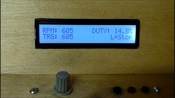
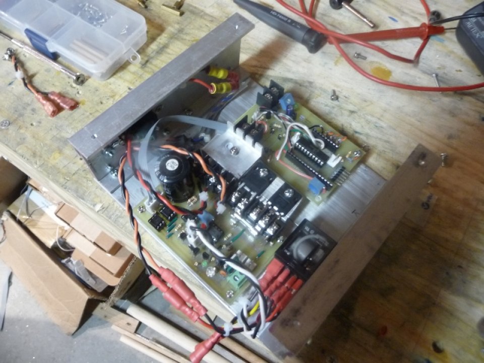
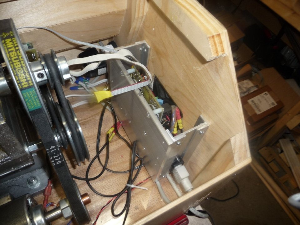
When building my Gingery Lathe the idea of belt changes to get different speeds didn’t seem very appealing to me, and thus I began designing this Motor Controller & Driver. The driver was designed to power a 2hp ( 2kW ) Treadmill Motor with fully rectified & filtered 120VAC, though with little to no modification you could drive any load as long as the drive voltage is greater than 12VDC. The Controller is PWM based, and uses a closed loop PID control algorithm for maintaining constant speed regardless of the load applied. The controller can also be setup as an open loop variable speed controller ( when using feed forward only ) if you don’t want to add the Tachometer. The Controller also provides a very nice 3 button interface with 24×2 character LCD.
Project Videos:
Controller Interface & Cutting Demo
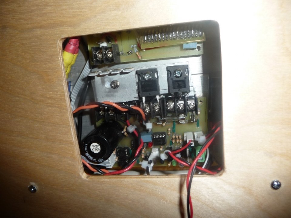
Project Photos:
If you do decide to download the project, by all means take the time to read through the README.txt file. I’ve put quite a bit of information in there and it will be a good starting point if you are seriously considering building this project.
Features:
- Controller & Driver on separate boards meaning you can either build just the Controller ( if you already have a driver ) or the Driver ( if you already have a controller ).
- Driver’s Controller I/O is optically isolated
- Controller can be setup for Closed Loop or Open Loop speed control
- Driver & Controller support Current Limiting
- Relay Based Motor Reverse – Less Mosfets Required
- Controller has nice 3-button + 24×2 LCD Display User Interface
- Spindle Indexing ( as of 12/16/2013 update )
Software Requirements:
- EAGLE 6.4 Free / Lite version
- MPLAB ( 8 or possibly MPLABX ) with Free C18 Compiler
Hardware Requirements:
- Soldering Skills
- PCB Making Skills ( toner transfer )
- PICKIT2 ( or PICKIT3 ) Programmer
What’s included:
- EAGLE schematics & board layouts for:
- Controller
- Driver
- Tachometer
- Special Connectors
- PIC18LF14K50 C18 Source Code
- Parts List
- Encoder Wheels
- README.txt – Lots Of Good Info
License:

This work is licensed under a Creative Commons Attribution-NonCommercial-ShareAlike 3.0 Unported License.
Download the Project:
Current Version: 1.2e

Changelog:
12/16/2013 – version 1.2d -> 1.2e
Added ‘Spindle Indexing’ capability to the Controller software. Also includes an updated ‘Tachometer’ design / board layout that should be used if you want to accurately index the spindle using this update.
Added ‘Spindle Indexing’ capability to the Controller software. Also includes an updated ‘Tachometer’ design / board layout that should be used if you want to accurately index the spindle using this update.
10/01/2013 – version 1.2c -> 1.2d
Changed Timer0 to operate at 500hz, and updated the current limiting code to incorporate a software based low pass filter in order to prevent false triggering from the PWM pulses. When the current limit detect count is greater than a set threshold current limiting will take effect. The current configuration allows the system to initiate current limiting at half the 1khz frequency of the 4/23 update which may correct some discrepancy Darren was seeing between his bike computer and the tach output. more data is collected per tick in order to determine if current limiting should take place.
Changed Timer0 to operate at 500hz, and updated the current limiting code to incorporate a software based low pass filter in order to prevent false triggering from the PWM pulses. When the current limit detect count is greater than a set threshold current limiting will take effect. The current configuration allows the system to initiate current limiting at half the 1khz frequency of the 4/23 update which may correct some discrepancy Darren was seeing between his bike computer and the tach output. more data is collected per tick in order to determine if current limiting should take place.
4/23/2013 – version 1.2b -> 1.2c
Found the Current Limit sample rate in software was not fast enough to effectively deal with stall situations when the controller was setup with TACHOMETER_ENABLED=0 and PID_ENABLED=0. Thanks Darren for building the controller and testing it out on your big lathe with back gearing. Anyways, updated the code to provide a dedicated 1khz sample rate on the current limit input which seems to be working quite well with my Gingery Lathe. In testing I locked the spindle, and increased the duty cycle to my max setting ( 50% ) the motor ended up spinning eventually ( belt slipping ) but you could audibly hear the current limiting working, etc… Nothing blew, and hopefully this will solve Darren’s issue with enabling his back gears.
Found the Current Limit sample rate in software was not fast enough to effectively deal with stall situations when the controller was setup with TACHOMETER_ENABLED=0 and PID_ENABLED=0. Thanks Darren for building the controller and testing it out on your big lathe with back gearing. Anyways, updated the code to provide a dedicated 1khz sample rate on the current limit input which seems to be working quite well with my Gingery Lathe. In testing I locked the spindle, and increased the duty cycle to my max setting ( 50% ) the motor ended up spinning eventually ( belt slipping ) but you could audibly hear the current limiting working, etc… Nothing blew, and hopefully this will solve Darren’s issue with enabling his back gears.
4/7/2013 – version 1.2 -> 1.2b
Added ability to use controller in open loop mode ( knob adjusts duty cycle with no PID closed loop algorithm ) via PID_ENABLED. Also added ability to disable the tachometer via TACHOMETER_ENABLED for those that do not wish to use one ( or build that aspect of the controller ). The controller updates the menu system dynamically based on the PID_ENABLED and TACHOMETER_ENABLED definitions.
Added ability to use controller in open loop mode ( knob adjusts duty cycle with no PID closed loop algorithm ) via PID_ENABLED. Also added ability to disable the tachometer via TACHOMETER_ENABLED for those that do not wish to use one ( or build that aspect of the controller ). The controller updates the menu system dynamically based on the PID_ENABLED and TACHOMETER_ENABLED definitions.
Added in Slow Start, and Slow Shutdown capability with STARTUP_DUTY_RAMP, and SHUTDOWN_DUTY_DROP constants. This will help smooth motor startup and shutdown, and hopefully reduce additional stresses on the components. To disable these simply set the RAMP and DROP to the ABSOLUTE_MAX_DUTY value.
Morgan
I’ve followed your build, one of the best I’ve seen. Good work and I think you have taken Gingery to a whole new level. I was looking at the download and there are some files that I do not recognize. Could you help me out?
Nelson
Hey Nelson,
I’ll drop you an email, and hopefully we can square things away with any file related issues.
Cheers,
Morgan
I started down this road about 15 year ago, but gave up after a couple attempts at some simple castings. (You appear to be mastering the art.) I figured it was cheaper in terms of time to just buy the import machines. But, your work and videos are an inspiration! This motor controller is quite interesting since I have acquired several 90V DC motors over the years that I would like to use on lathes/mills etc. I will certainly be studying what you have done.
Hey William,
Thanks for the comment. For me most of what was required – casting, hand scraping, etc… were all fairly new to me, and it was definitely an uphill battle at first. Perseverance definitely paid off, and I’m happy I stuck with it. Looking back now, I would possibly have bought the import lathe as well, though I would have been less motivated to learn how to cast aluminum at that point. Let me know if you have any questions on the controller / driver.
Cheers,
Morgan
Thanks Morgan for sharing your hard work for all to use. I know a lot of time and hard work has went into this, not to mention packing it in such a nice download with all the info and parts list. (hope i can grab my parts before Mouser changes part numbers on me)
I have about finished my patterns for the Gingery Lathe with only the last couple yet to make. Hope to have all poured and hopefully scraped and fitted by early Spring. I’m still looking for the tredmill for a motor, locally. May just explore the internet for a motor and eat the shipping cost.
Have downloaded your build files and you have really done us laymen a great gift. Truely appreciate all the info and hard work you’ve shared. I’d love to build this project not only for the Gingery lathe and mill, but for having it to drive most anything needing power that a large 2hp motor will work on. I’m a tinker-er and love power when needed and have lots of projects this may come in handy for.
Only a couple of questions or thoughts.
1- Looking over the drawings i’ve seen a need for 5volt and 12volt power inputs. Not as up on electronics as i used to be, and from a quick view, looks like i’ll need some 12 and 5 volts coming from somewhere? 12-30volts and maybe a 5volt tap off somewhere from that? Do you know of or can reccomend a power supply, cheap and normally stocked somewhere or maybe a layout to make one?
2- My lathe should i ever get through with this one i’m building, i’m hoping will drive a few maybe heavy chunks of metal should the need come up. That said, some will need RPM’s of extra low speed and some may even be slightly out of balance. With that in mind, my thoughts go to a moment of panic should the driver or controller get pessy on me and try and jump full thottle on me. Looking at the diagrams, this in my lowly educated means would be near impossible with the motor take-offs the way they are. Yet are my thoughts mere bone head, or is there any possible way this could happen? Resistors do burn, capasitors leak, and transistors can fry. We all know man made and machine made, and good bad and ugly waits in line on everything.
Know you’ve had great thing with yours and hope mine turns out as nice. Hope to make mine a bit portable if possible to plug into ether my lathe or the mill i hope to make.
Thanks again for the download and the sharing.
Rick.
Hey Rick,
Thanks for the comment, and kind words about my effort getting the files online. I put enough time into it I felt it was an obligation to myself to at least get the information online. Also, I had committed to it at various moments on the Gingery Machine Yahoo group and wanted to follow through.
Definitely don’t worry about Mouser, they are pretty good at stocking items. If anything becomes unavailable the datasheet / information on the part should remain online and you can try and find an alternative ( or ask me and I can source one for you ).
Awesome on the lathe status, sounds like you are making excellent progress!
I have found the best play to buy treadmill motors nowadays is ebay, this guy has a bunch reasonably priced with shipping:
Ebay Store With Treadmill Motors
If I ever need to buy another motor I’ll probably get one from him as he seems to be the cheapest source I can find right now.
To your questions:
1. It has been my goal to isolate the Controller’s power supply from that of the Driver. Instead of building a power supply I cheap’d out and purchased some wall chargers from my local recycling resale store. For the 5V supply I use a typical cell phone charger – cord cut to get to the wires, and I was able to also find a cheap 12V wall wart. It’s not the most ideal, but was a cheapest solution ( total cost $9 for both ), and the power supplies are definitely isolated from each other. Not sure a tapped transformer would give you the same isolation as having two separate transformers, but I would have to research that. You could definitely use a PC power supply, or buy something like this CFM40D +5V, +12V Power Supply however I believe on this one you won’t be getting isolation between the +5 and +12… It would be more affordable to build your own supply with dedicated transformers for each voltage level ( or just do what I did ). If using a regulated +12V at the input of the driver be sure to jump 12VREG to override the LM317 ( voltage regulator on the board ).
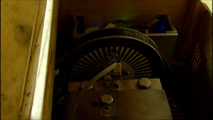
2. By ‘Extra Low RPM’ what numbers are you looking for? I can cut metal right now at 60RPM, though not ideal. There are two concerns that need to be addressed when getting down to say 5rpm. First is the encoder wheel resolution. Currently I have a 96 res. wheel and my sample frequency in the Controller is set to 96hz. At 60rpm, we are looking at one rotation per second, and a transition count of 1 at each sampling time. Anything below 60rpm will produce a setpoint of less than 1 which is extremely fuzzy unless you increase the resolution of the encoder wheel, or decrease the sampling frequency. The controller code uses floating point, and it will still produce 5rpm, but the rotation of the spindle will not be smooth, which you don’t want on a lathe. The encoder wheel resolution issue could be resolved by mounting the encoder wheel and tach on the motor spindle itself ( unless you are using a 1:1 pulley ratio, not recommended ). Also, with a 1:5 pulley ratio I have found that at low rpm ( 60rpm for instance ) the PID controller needs to have fairly aggressive constants in order to respond to a load being applied to the spindle – once in the cut however a steady state will be reached. If it was my goal to cut at say 10-20rpm on the lathe I would either swap out my 5″ diameter drive pulley on the spindle for a 10″, or I would add another shaft between the motor and spindle for another reduction ratio – something like 1:5, 1:5 – if a 10″ pulley wasn’t practical for instance. I also notice that most treadmills have a flywheel, and I never had one on mine. Using the flywheel would probably help quite a bit with drastic initial changes in load.
I have turned a few things that were out of balance ( though not ‘extra heavy’ ). The machine handled it fine, however everything was shaking quite substantially. I fixed this by adding counter balancing weights on the faceplate which worked beautifully. That being said, the controller / driver has no problem handling intermittent cuts, or out of balance turning – it’s more the machine itself and it’s rigidity I’d imagine.
I have definitely tried my best to make the system as ‘safe’ as possible, though there could be things that I missed. There is a 15A fuse in series with the motor, and I have found that, when I was blowing mosfets, the fuse would blow fairly quickly stopping the motor. There is a pull down resistor at the Mosfet Gate of 1meg to tied the gate to ground in the event that the gate drive resistors blow ( never has happened ). Of course if T2 fails in the Driver, the Mosfet will be always on, which would cause the fuse to blow. I’ve never had any of the electronics on the Driver fail thus far however other than Mosfets blowing prior to my implementation of current limiting. I have had some instances early on in the design of the High Voltage going back through the Dead Mosfet ( typically die short circuit ) and blowing some of the components closest to the Mosfet – gate resistor, T3 or T4. The other places of possible failure could be the current sensing resistor ( RSENSE ), however if that failed it would fail open circuit and probably would tie the motor to ground through R12 ( 1k ) and the Comparator. R12 would blow instantly as it is low wattage and then the motor would have no path to ground and would stop. There could be potential damage to the Comparator in that case. I do use IC headers so I can easily swap out components if need be, but I haven’t needed to up to this point.
The software itself has some safety features built in as well. In the even of a stall on the spindle the system will timeout and stop the motor. This can be adjusted in software in the ‘main.c’ it’s the ‘#define STALL_TIMEOUT = …’ line. Current limiting is also a critical component of the Controller, and you’ll find at times when you start the the spindle from a dead stop the ‘|CL’ will show up briefly due to the motor’s startup current. I was thinking of implementing soft start in software, but with current limiting properly tuned this is no longer required. The software also has ‘Max Duty’ which allows you to clamp the PWM duty to a maximum. I’ve found that for what I’ve done thus far clamping it to 50% on a 2hp treadmill motor works fine. I would recommend during the testing phase to set this to 10-25% until you are sure everything is working properly.
—
Thanks again for the comment, and I hope this information is helpful. Definitely don’t hesitate to ask more questions, etc… I’d be glad to help.
Cheers,
Morgan
One more thing, I forgot to mention – and is also not in the project files, definitely setup an emergency stop switch. This is similar the one that I use:
http://compare.ebay.com/like/170520711348?var=lv<yp=AllFixedPriceItemTypes&var=sbar
Basically it has two terminals – one is normally closed, the other normally open. When pressed down the button locks and the status of the terminals are switched from open to closed.
I have mine wired up such that one line of of the motor is connected to the ‘normally closed’ terminal, such that when I press the button power is cut off from the motor.
Thinking about it, I could have also connected the 120VAC input to the other ‘normally open’ terminal, and then when pressed it would also cut off the 120VAC source as well – however the capacitor would still have a voltage potential, but that would bleed off fast if there was still anything connected to it ( motor wise ).
—
Cheers,
Morgan
Hi Morgan
Great project, well documented and I admire your sticking with the gingery lathe most would have given up in the casting side of things.
I`ve built you your schematics within proteus on a single board all works as expected but I don`t require the tacho, how would I go about making this a variable speed drive only with no feedback?
cheers
Darren
Hey Darren,
Thanks for the comment, and glad you are interested in the Driver / Controller project.
Are you planning on using the ‘Driver’ exclusively, or will you also be using the ‘Controller’ in the project. If you will be using the ‘Controller’ the software will need to be modified a bit to work as a variable speed controller without tachometer feedback. If you were planning on using the ‘Controller’ from the project, I would have no problem updating the code and putting out the open loop / no tach version for you – just let me know. If however you will be using your own controller, or even a simple 555 timer with potentiometer, you would feed the PWM single to the PWM input pin on the driver board ( it’s in the 5 pin header to the left of the board’s schematic ). The driver has ‘Current Limit Out’, and ‘Reverse Control’ lines as well, though you may not need those for what you are doing – in that case you could modify that section of the board to accommodate your own ‘Controller’ possibly reducing the number of traces / components needed on the board. Since the current setup has Current Limiting under software control, you could always design a simple circuit to pull the PWM input signal to ground when ‘Current Limiting’ is detected, etc…
Let me know I’d be glad to help,
Cheers,
Morgan
Hi Morgan
Thanks for your reply, I`ve built your complete design on a single board with 240v ac in and a step down transformer 20v pcb mounted into a small bridge smoothing cap and then a 7805 feeding the lm317lz, The other side of isolation is powered off board (I could`nt squeeze another tranformer in with my size limitations maybe in the future). Main motor power is 240v in feeding a MP3510s bridge and two 220uf 450v caps, other than that the circuit is yours. If it`s not too much trouble I would really appreciate if you could modifiy the code for me. My programming lacks to say the least.
Many thanks
Darren
Hey Darren,
No problem on the reply, very cool on putting everything on a single board with power supply. For rectified 240v, make sure you have a decent heatsink on your mosfet, and I would also recommend a fan. You may also need to source a larger mosfet, or update the board for multiple mosfets in parallel to handle the additional current. How big is your motor ( either hp or kilowatts ). I’ll try and get an updated version of the code for you built, and tested, sometime this week.
One question, for the controller’s display, as an indication of the speed, would you want it to still show an RPM number which would be based on what you set as the ‘Max RPM’ and the knob position, or would you simply want 0%-100% as the output on the LCD? I could also do a nifty bar graph probably to indicate the knob’s speed setting. Let me know.
Cheers,
Morgan
Cheers Morgan
your a star, the motor is a 1 1/2 hp treadmill motor which is set up on a 1952 Boxford (southbend clone) it was running with the original controller, I made a 555 pwm and managed to get it to work for a bout 2 years but something blew on the daughter board (smd no hope fixing that) anyway to cut a long story short I made a couple of basic boards but kept blowing mosfets I was so chuffed finding your site. Given me new hope.
The Mosfet i`m using is a W20NK50Z 500v 17amp, the RPM would be good to have it based on max rpm.
many thanks
Darren
Hey Darren,
I’ve got the code pretty much modified, though it isn’t online yet. I’ll try and test it out later tonight. I added two new constants with some pre-processor conditionals to modify the code such that I wouldn’t have to fork the code into a ‘open loop speed controller’ version. Anyways, looks good and I have enables for both PID and TACHOMETER, such that you could have the controller operating in open loop mode ( knob varying duty cycle only ) and still have the Tachometer working if you hooked one up. You can also disable both PID and Tachometer, at which point it is strictly variable speed at the knob with no feedback or actual RPM display. It’s nice because I have the code setup to adjust the menu system accordingly depending on what is enabled.
Once I have it updated, I’ll update the code on the projects page and will drop you a message, or reply again to this comment.
Do you have a PIC programmer? If not I could always mail you a PIC with the software programmed on it. Let me know, though a PICkit2 ( or 3 ) is definitely nice ( and fairly cheep ) if you plan on doing any PIC micro-controller work.
Cheers,
Morgan
Hi there Darren!, I’m from Italy and I want to build the made by Morgan.
Morgan said to me that you have a modified version of it….Do you have a Schematic and PCB trace of it??
Let me know…many thanks!
Hi Morgan
I`ve got my lathe back yippe.
Bench testing was spot on, hooked it up to the lathe and hey presto she span up, took it up to 400rpm then lowered the speed and tried to slow the chuck, I could`nt. once it is set up properly i`ll send some pictures. Thankyou for sharing this project and taking your valuable time to meet my needs.
all the best
Darren
Hey Darren,
Fantastic work! I’m glad everything went off without a hitch, and believe me it was my pleasure to help. It is extremely exciting to know that someone else out there has built, and wants to use, a project that I made available. Definitely let me know if you need anything else, and for sure more pictures, a video, or anything else you might have of it setup and running would be totally awesome and appreciated
Cheers,
Morgan
Hi Morgan:
I am planning to buy the Treadmill Motor C3354B3909, Part #: M-295727 is 2.75HP 130VDC, do you think that work with your design?
This is the link for the motor
http://www.ebay.com/itm/170983382367?ssPageName=STRK:MEWAX:IT&_trksid=p3984.m1438.l2649
Thanks
Hi I love your videos and was trying to download your file to make my own speed controller but the files would not download. If you could fix that or just send me the file via email that would be great.
Thanks
Jeffrey Krupke
If you want to call and chat my number is 907-315-5526
I’m up in Alaska
Hey Jeff,
Glad you like the videos, it’s appreciated. Sorry about the download issue, it should be fixed as of now. I’ve never been to Alaska, but sounds awesome – my wife went on a cruise there once and loved it. Let me know if you have any questions about the controller.
Cheers,
Morgan
Morgan,
Amazing! You are doing all the things I have always wanted to do and I just had to say thanks…
I hope to be working with your DC motor controller soon.
Hi Morgan Amazing
I hope to be working with your DC motor controller soon i have lot of Treadmill Motor I’ve been searching for Controller & Driver
can u share your design at http://www.cnczone.com
Hi Morgan,
I plan to build your controller, but my PIC programmer does not support the 18LF14K50. Not sure if I want to buy a PICKIT2 only for this project. Do you know if it will be easy to port the code to another (older) PIC? Or do you have some pre-programmed PIC in hand that you can sold?
Regards