Quite a bit has been accomplished on the lathe since my last post, and this will most likely be more of a summary to catch up to where I am now. I’ve been able to complete the Gingery Lathe Tailstock as described in Book #2, and in the process, built the required accessories to complete the job; a setscrew faceplate, clamp dog, etc… I was on the version 4 iteration of my driver electronics, and half way through the tailstock build ( and after blowing many a mosfet ) realized it was finally time to implement current limiting ( something I should have done from the start ). I was also getting a bit tired of working with the ATX case for the driver, and built a new case out of aluminum, which also acts as a big heatsink for the driver’s mosfet.
I’ve created two complete videos of the Tailstock Build and Faceplate Build. I usually post the links at the bottom of the post, but I’ll put them up here if you would rather watch a videos…
Videos:
a. Making A Setscrew Faceplate Video »
b. Making The Gingery Lathe Tailstock Video »
Faceplate
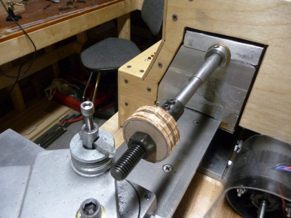
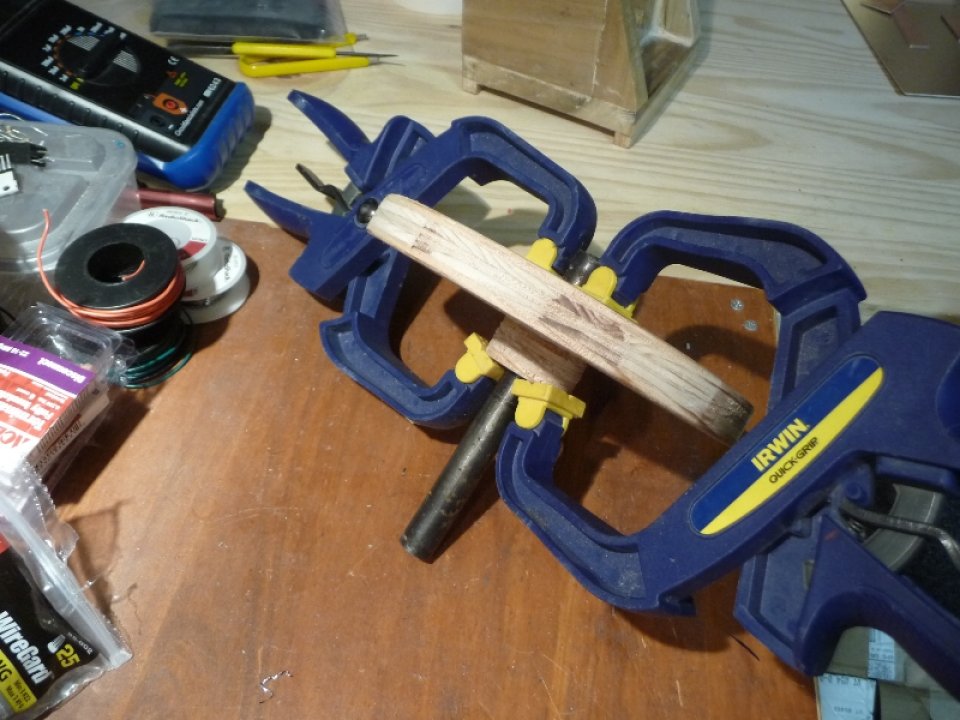
The faceplate is made from 3/4″ plywood, with a 3/4″ hub to accept a setscrew for mounting on the lathe spindle. Dave Gingery’s Book #2 has a smaller faceplate than the one I made, as I already have Book #6 and he suggests building a bulkier faceplate. The faceplate pattern was mounted on the lathe spindle boring bar with a threaded shaft adapter, and turned down with the lathe ( one of the first actual turning operations on the lathe, yay ).
Photos of faceplate pattern being built:

I don’t really have any photos of the molding / casting, however I do have it completely documented in the video link above. Here are some photos of the cast Faceplate.
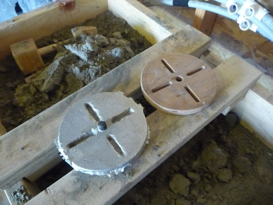
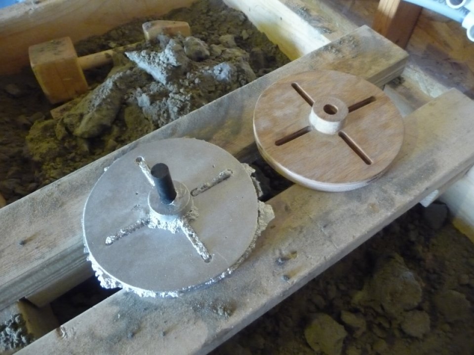
With the faceplate cast, the steel core was hammered out, and a 1/4-20 setscrew installed on the hub. The faceplate was then mounted to the lathe spindle, hub turned down, front and back faced off.
I didn’t bother with finishing cuts yet, once everything was trued up I mounted the faceplate in the milling machine to cut the slots. Originally the slots where to be 5/8″, but the sand cores didn’t come out so well and I wanted complete contact through the 3/4″ faceplate. I ended up enlarging the slots to 1/2″.
Photo of the slots being milled, and checking that they are square:
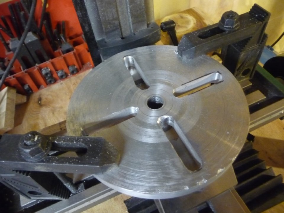
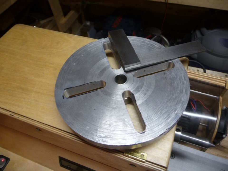
Photo of facing off the front, and the final faceplate:
The completed faceplate was then verified to be square with the lathe spindle, bed ways, and cross slide ways.

Clamp Dog
You need something to drive a piece of stock between centers, and a clamp dog was created with 1/2″ square CRS & 5/8″ bolts. A ‘V’ was cut in the middle to provide grip on round stock.
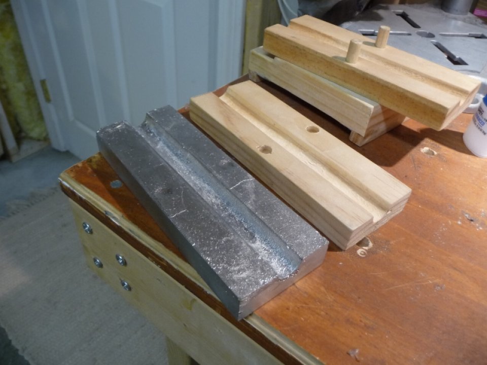
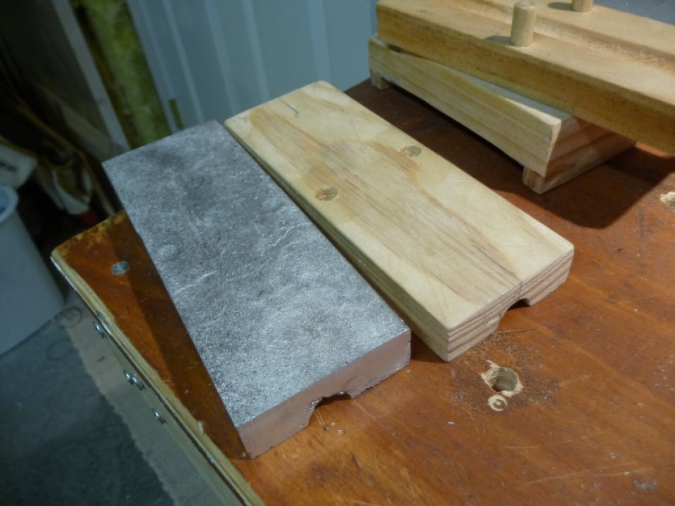
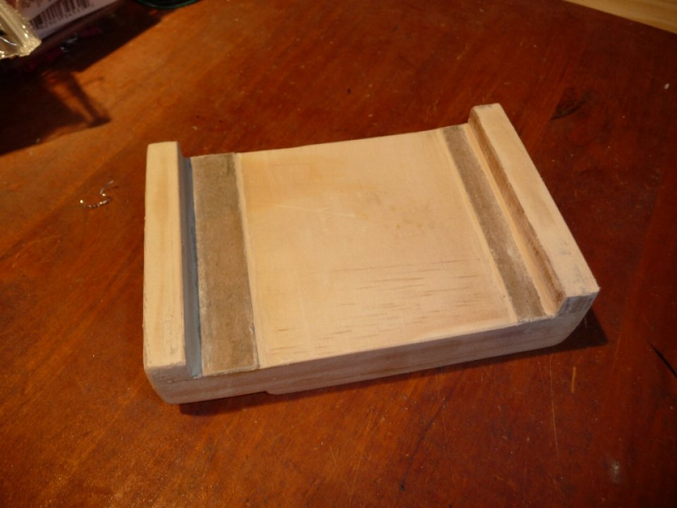
5/8″ Corebox
The tailstock barrel is 4″ long, and it would be rather difficult ( as suggested in book #2 ) to drive out a steel core that long. Gingery suggests building the required tools to make a sand core. The corebox was constructed from 3/4″ pine stock, and dowel pins used to ensure that the two halves meet up exactly when assembled. A center line was cut down the two halves ( and Xacto & Straight Edge do the job ). The center lines were then filed to a ‘V’ with a 3 corner file, and the halves clamped back together. The ‘V’ center line acts as a pilot hole for a 5/8″ spade bit. Since the box is too big for the bit to cut all the way through, I had to cut from both sides and the ‘V’ groove did a decent job at keeping it all on center.
The process of making a sand core is similar to that of molding a regular pattern for casting. Instead of green sand, a different mixture of water, wheat paste, sand, and molasses is uses to make the core ( it took me a while to hunt down wheat paste locally – start in the phone book with wall paper stores, not hardware stores ). A wire that runs down the length of the core is used for reinforcement. The core needs to remain a true as possible, and would sag if baked outside of the box, so one half of the corebox was cast in aluminum to provide a baking tray. Once the sand core is made and transferred to the baking tray, it is baked at 350 deg. for 1 hour.
Photos of core box & baking tray casting:

For a better idea of how the sand core is made & baked checkout the tailstock video above.
Tailstock
The tailstock was built as suggested in Book #2, though the base was scaled up to fit my lathe’s 4″ wide bed ways. The first order of business was to make the base pattern.
Photos of Tailstock Base Pattern ( checkout video for casting ):
The Tailstock Base casting was cleaned up on the milling machine, box clamp created in a similar fashion to that of the headstock, and 3/8-16 clamp screw installed. A piece of 1/4″ x 2″ CRS was cut to size for the setover ways. Two mounting holes were drilled to 13/64 in the ways, and then the ways were clamped to the base. The ways were then used as a guide to drill the mounting holes into the base casting. A piece of 2″ angle iron, a machinists square and straight edge were used to get the setover ways perpendicular to the bed ways. The setover ways mounting holes were then drilled to 1/4″ and countersunk. The holes in the base casting were tapped for 1/4-20 bolts.
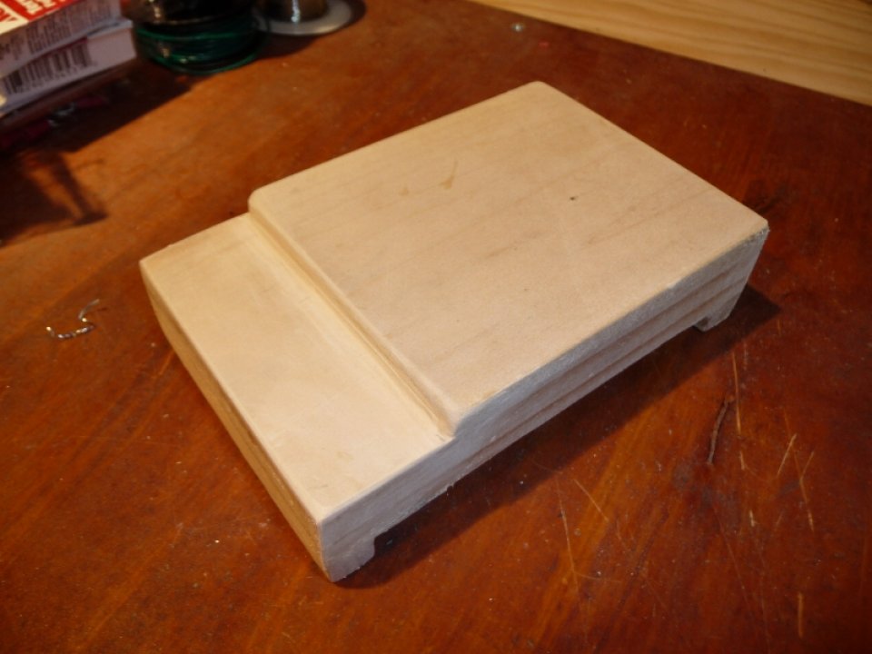
With the Tailstock base installed, a digital caliper was used to determine the required height from the top of the base to the center of the lathe spindle. This measurement was used to build the top tailstock pattern, as it will be essential that the tailstock barrel’s bore be as on center with the spindle as possible for the boring operation.
Photos of the Tailstock’s Top Casting:

The rough tailstock top casting was cleaned up on the milling machine. The setover bolt hole was located on the setover ways, and then that location marked out on the tailstock top such that the slot could be milled. With the slot milled the tailstock top was placed on the setover ways and the bolt location punched while the top was in place ( to ensure that the bolt will be on center with the milled slot ). The bolt hole in the base was then drilled to 5/16″ with the setover ways mounted to the base. The hole was tapped for 3/8-16″ and the setover clamp bolt installed. The setover screw holes & gib screw holes were located on the tailstock top and drilled to #25 ( or 13/64″ ) for a 10-24 tap. A piece of 1/4″ square keystock was used for the setover’s gib.
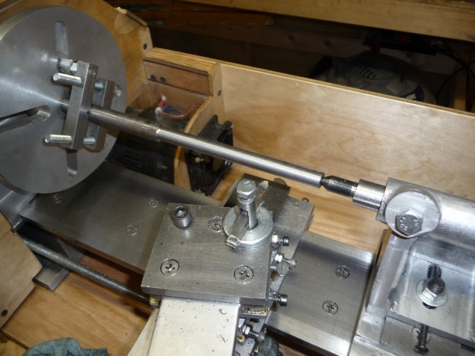
With the tailstock top fitted to the tailstock base, and setover adjusted such that the bore in the tailstock barrel would be on center with the spindle boring bar, it was time to bore the tailstock barrel to 3/4″. The boring operation was basically the same as that of the headstock, though this time around the leadscrew was connected to the spindle via reduction pulleys for a basic automatic leadscrew feed. This definitely worked quite well, and sped up the operation by quite a bit.
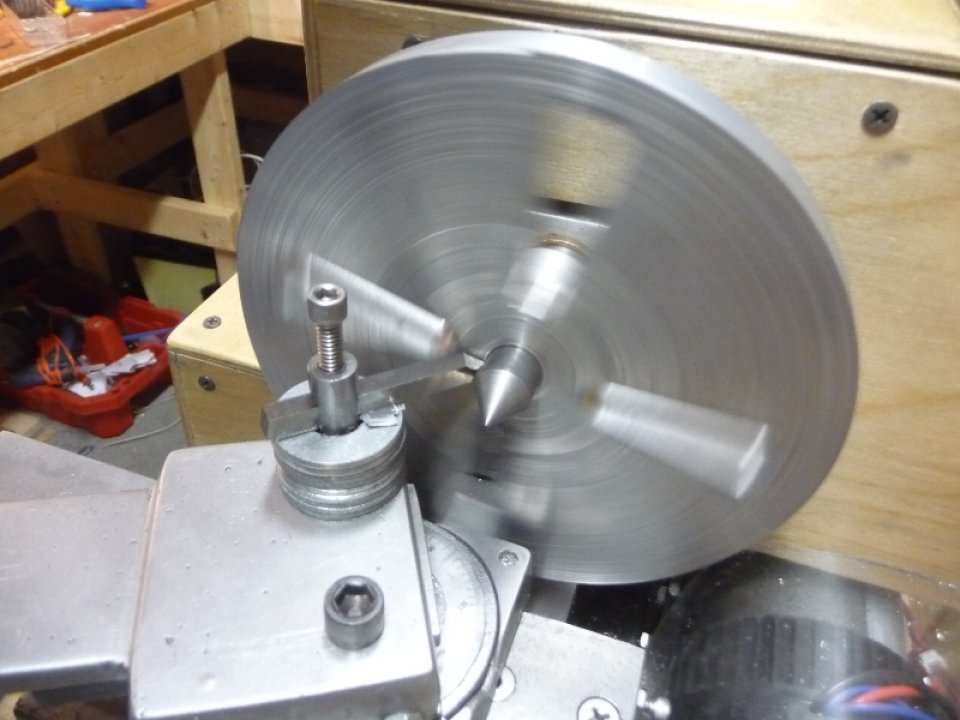
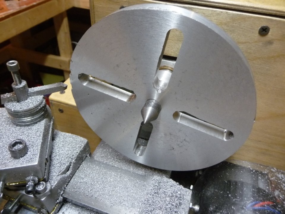
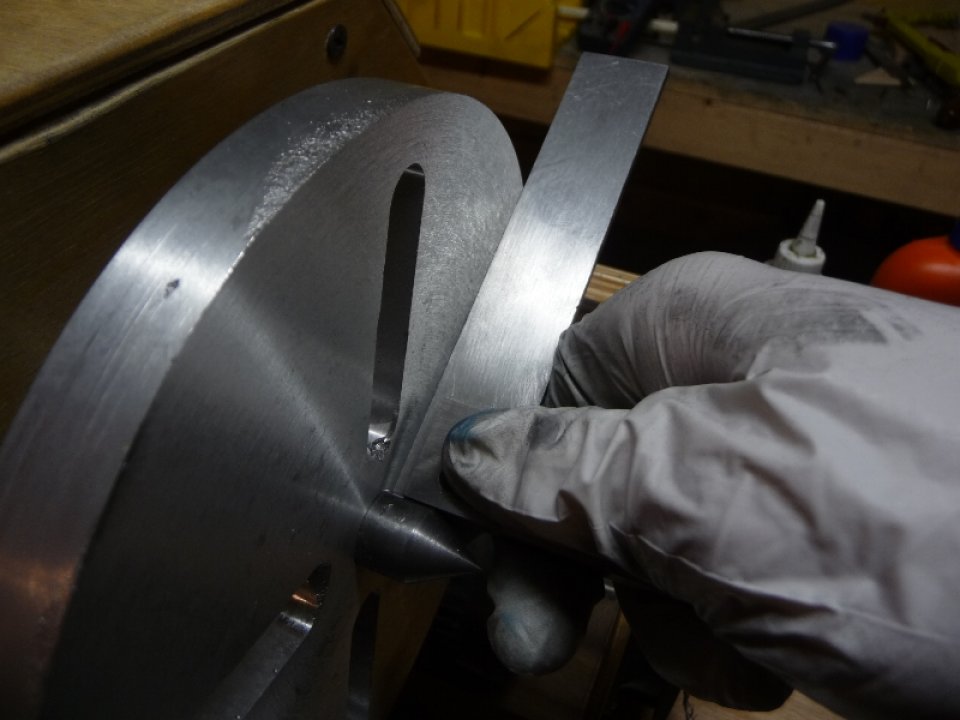
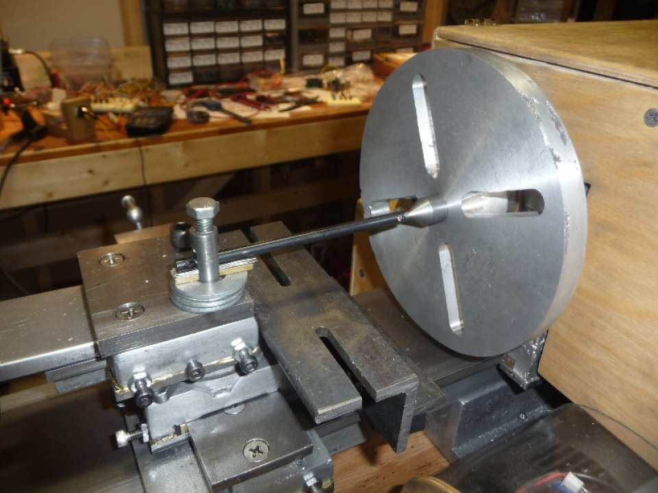
With the tailstock bored to 3/4″ it was time to setup temporary 60 deg. centers for the headstock spindle and tailstock ram. The temporary tailstock ram is a piece of 5/8″ round CRS, which was installed as a spindle and the end turned down to 60 deg. on the lathe. I used a 60 deg. center gauge to dial in the taper. The same procedure was used to produce a 60 deg. center on a temporary spindle. 3/4″ to 5/8″ flanged bronze bearings were used to bring the tailstock bore down to 5/8″ for the temporary ram.
Photo testing the tailstock center with headstock center:

With the two centers in place, a piece of 1″ CRS was turned down to 3/4″ for the permanent tailstock ram. In the process of turning down the stock, the centers were tested for parallelism by taking light passes, checking diameter on each end, and then adjusting the tailstock setover until the diameter on both ends of the stock were the same.
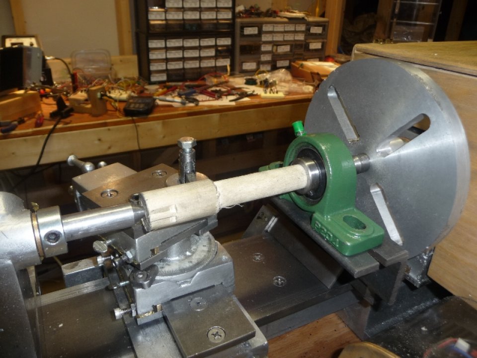
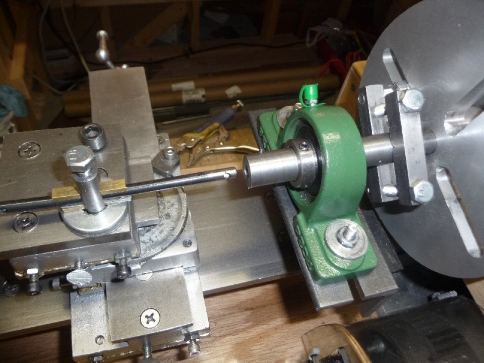
With a length of 4″ CRS turned down to the 3/4″, it was time to bore MT1 taper. A 3/4″ pillow block bearing, mounted to one half of the temporary headstock base, was used as a temporary steady rest. To get the pillow block on center, a 1″ dowel was turned down to 3/4″ and mounted between centers while running through the pillow block. Initially a through hole was drilled through the ram with a 1/8″ drill bit driven by an electric drill spinning in a direction opposite to the lathe spindle. The Gingery book suggests that this will keep the hole on center, and amazingly it did ( since the hole has to be drilled on both ends to reach all the way through ). One end of the ram was enlarged to 5/16″ to provide clearance for a 1/4″ boring bar.
Photos of setting up Pillow Block:
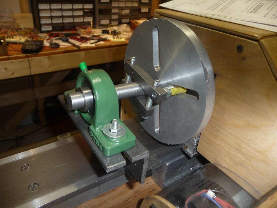
To bore the MT1 taper, the pillow block was initially setover by 0.053″ with a dial indicator + mag base mounted to the lathe bed ways. After boring to a point where an MT1 dead center could be inserted about 25% of the way, the dial indicator was used to determine the shank deflection. The deflection was divided by two, and the pillow block was adjusted accordingly. It only took a few tests to get the taper dialed in.
Photos of boring MT1 Taper:
With the tailstock ram bored to MT1, the other end was enlarged to 5/16″ and then tapped to 3/8-16. A keyway was cut down the length of the ram on the Milling Machine with a 3/16″ end mill. The book says this can be done with a hacksaw, and three corner file.
The next order of business was to turn down the ram’s feedscrew. With 1/2″ CRS round stock mounted between centers the feedscrew was turned down to the dimensions suggested in the book. I also machined the key for the keyway at the same time ( 5/16″ large end, 3/16″ keyway end ). The keyways prevents the ram from rotating when the feedscrew drives the ram in and out of the tailstock barrel. 3/8-16 threads were cut in the feedscrew with a die. I have had a 2″ ball crank sitting around for quite some time, and I took the time to clean it up with a mill file, and install a 10-24 set screw. The ball crank was installed on the feedscrew, and the whole setup was tested.
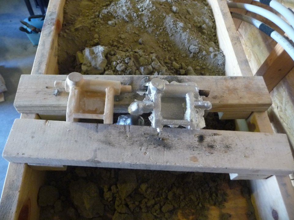
The final part of the tailstock build was the end bell, which secures the feedscrew at the back side of the tailstock. I needed some 1-1/2″ round stock for the end bell, and it was just my luck that Restore had two fancy aluminum rims for sale ( $10 a piece ). I quickly picked those up and melted them down into some rough cast round stock to be used on the lathe. One of the 1-1/2″ – 8″ length round castings was mounted between centers in the lathe and turned down to 1-1/4″ at the large end, 3/4″ plug side. The end bell was then cut from the stock with a hacksaw ( I need a cut off tool… ), and then the saw marks cleaned up on the milling machine. Two mounting screw holes were drilled into the backside of the tailstock barrel, and then the end bell installed and mounted with two 10-24 setscrews.
The final part of the tailstock build included drilling the tailstock clamp screw boss to 5/16″ and then taping with a 3/8-16 tap. The key was to ensure that the clamp hole would be exactly on center with the barrel’s bore such that the key would fit into the ram’s keyway. The key was placed in the hole, and then a 3/8-16 bolt installed to finish the tailstock.
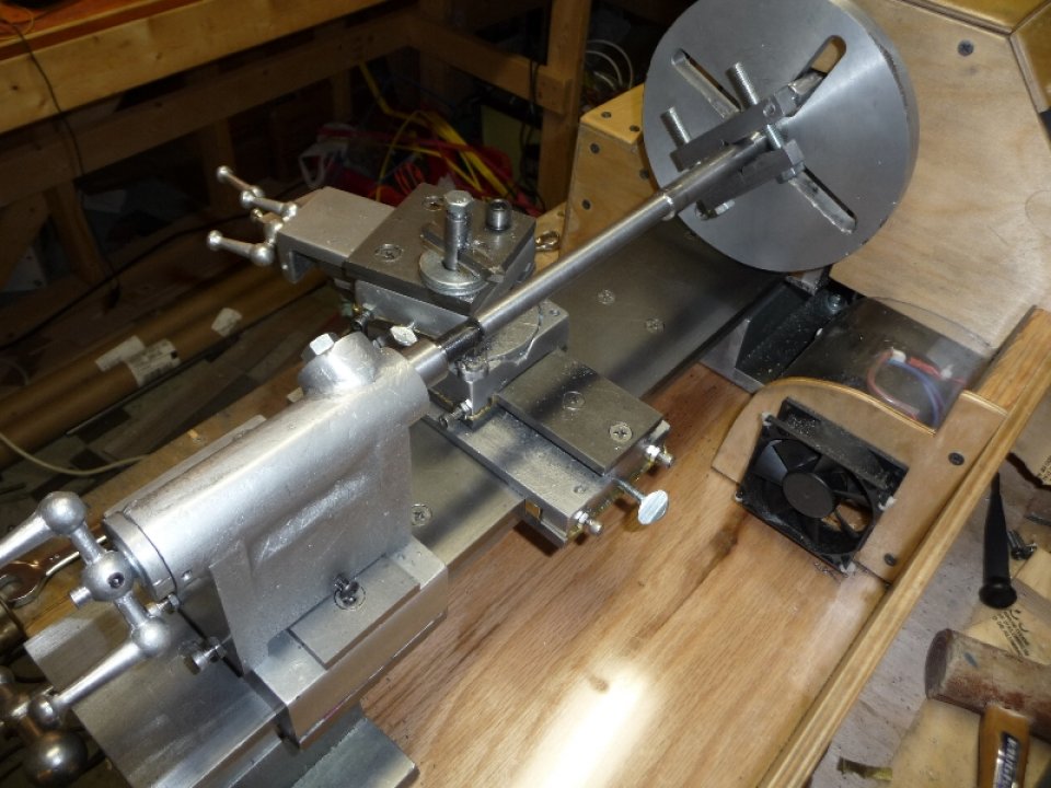
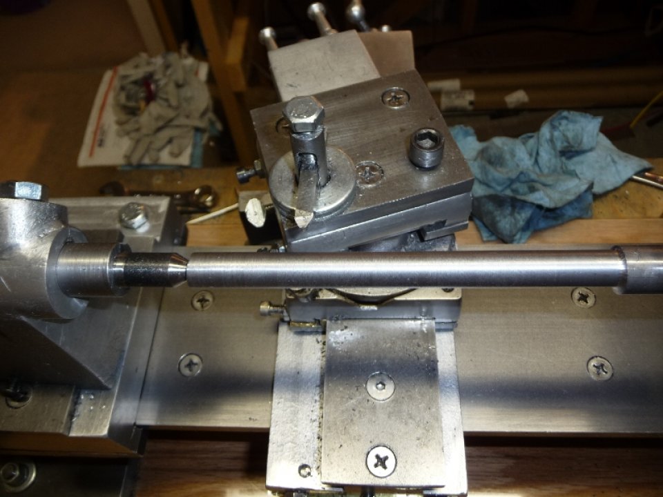
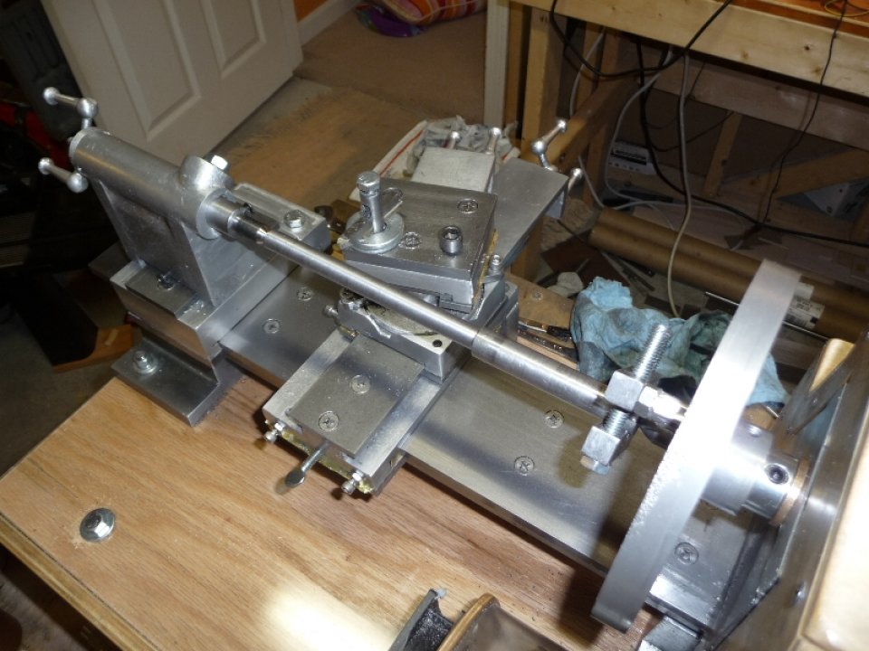
A fresh piece of 5/8″ CRS round stock was mounted between centers, and turned down with the new tailstock ram holding an MT1 dead center. The parallelism test was done again, and tailstock setover accordingly.
Photos of Completed Tailstock and Final Parallelism Test:
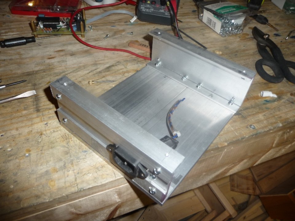
v5 Driver + Aluminum Case
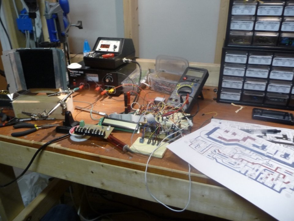
Halfway through the tailstock build, during the boring operation I quickly burned through 5 mosfets ( of varying sizes & capabilities ). I decided that it was about time that I upgrade my driver circuit to provide current limiting capability. I also was tired of opening / closing the ATX case I had for the v4 driver, and it was also hard to fit a large sized heatsink in there ( I also wanted to get my controller in the same case as the driver ). I ended up building a new all aluminum case that would also act as a big heatsink for the driver mosfet.
Photo of Testing v5 Driver On Breadboard with small 12vdc motor:
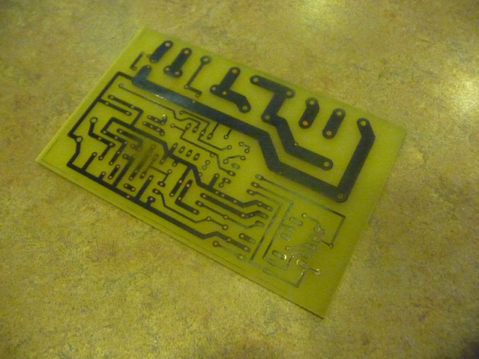
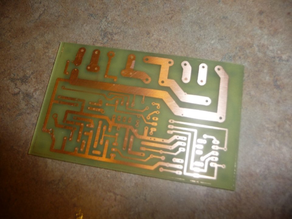
Photos of etching v5 Driver Board:


Photos of v5 Driver Board coming together:

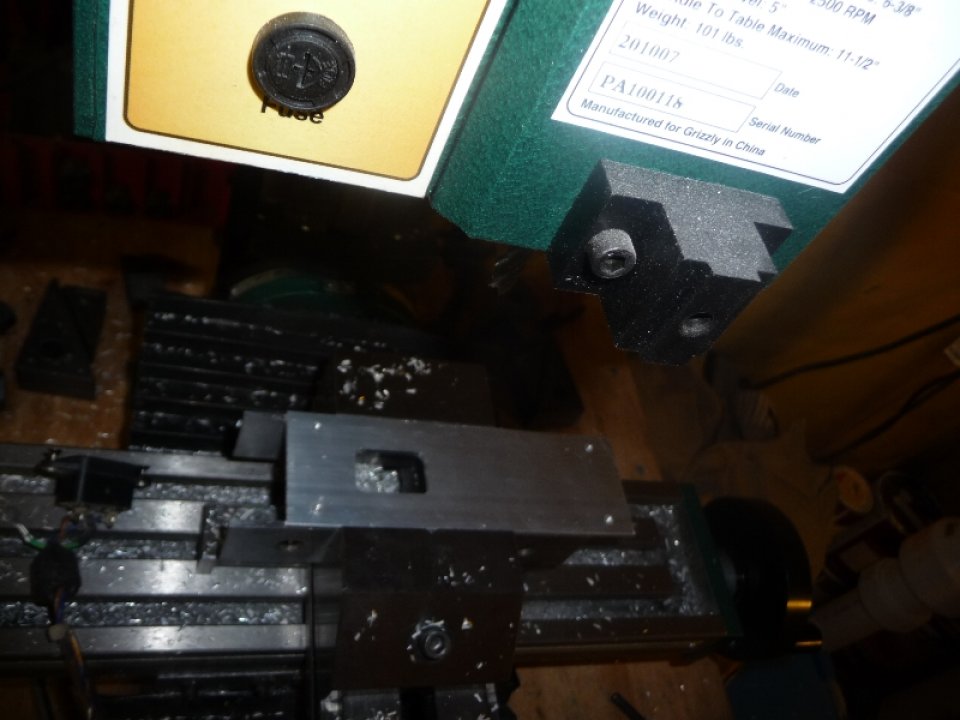
Photos of new Aluminum Case:
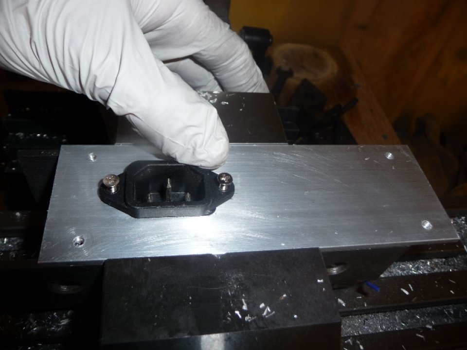
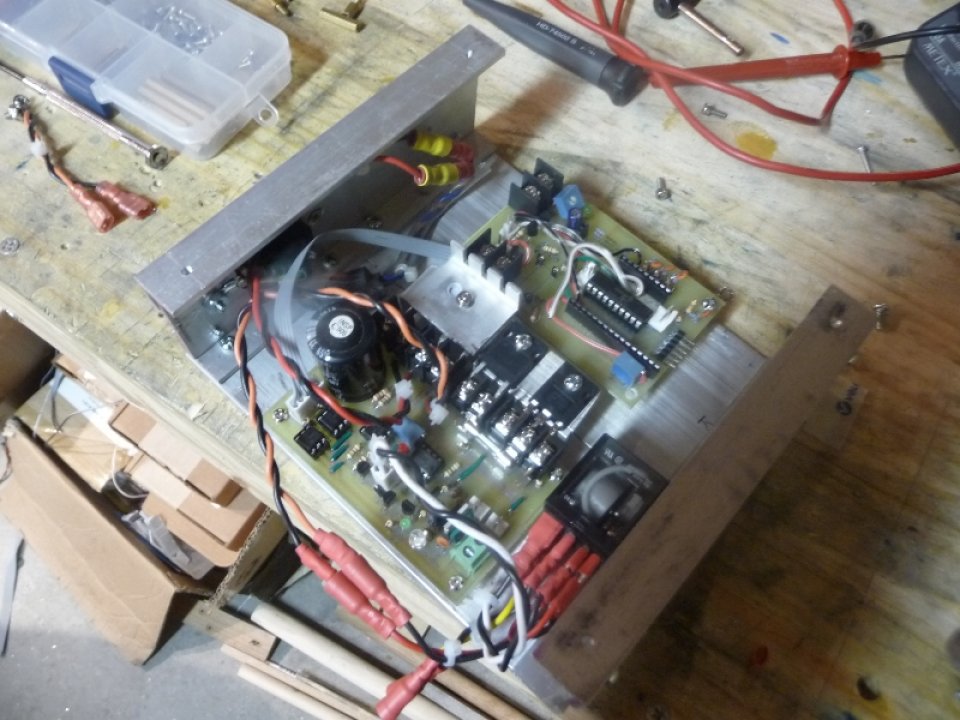
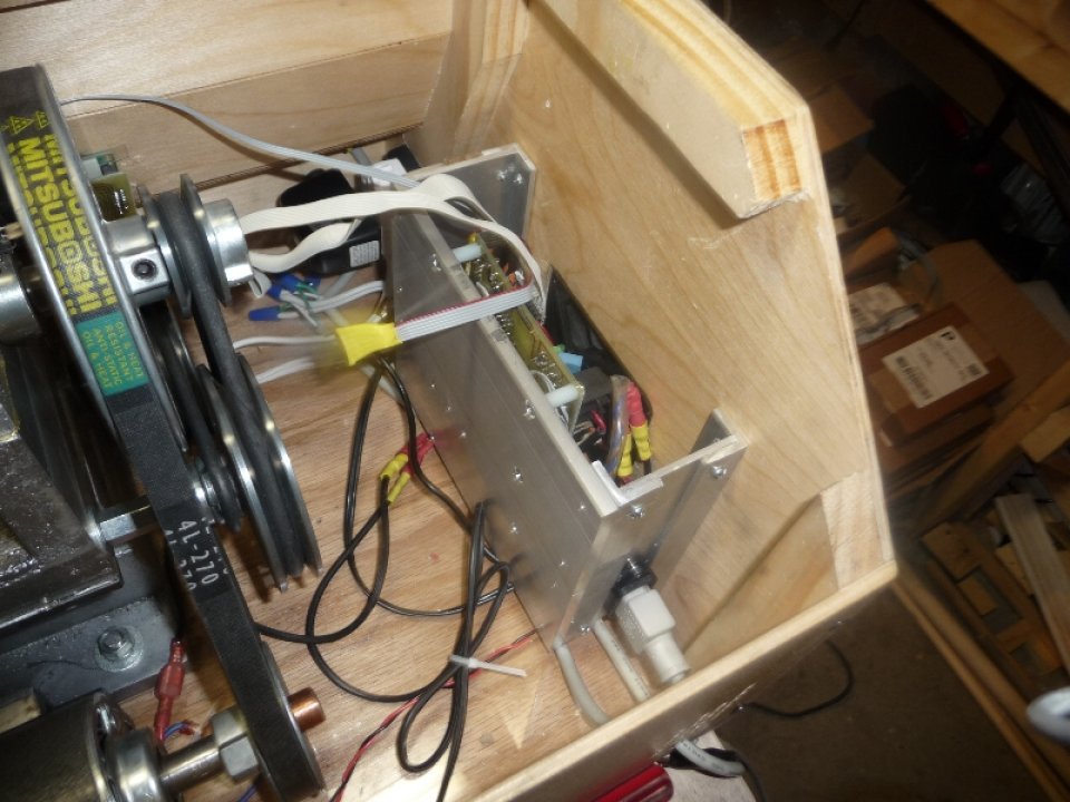
Photos of current Aluminum Case with Electronics:
Well that just about wraps up where I’m at now. I have some rough castings of a 2-jaw chuck, and a setscrew chuck that need to be machined. Once done I’ll definitely make a post on those, and will also be turning down the permanent spindle.
Also, hopefully at some point very soon I’ll be uploading the schematics, board layouts, PIC C18 code, etc… for both the driver & controller.
Finally, if you are interested in the Gingery Lathe, or any of the other ‘From Machine Shop from Scrap Metal’ books checkout the best source of information on the subject:
Gingery Machines Yahoo Group »
Cheers,
Morgan
very good job! but you have arleady a milling machine ,so it speeds things.Continue giving some pictures of your job.I have arleady made some parts ofthe lathe, but I’ve stoped last year,because I started a new hobby.
Hey, Thanks for the comment! Keep at it, my wife just purchased me the milling machine when I started working on the Headstock, everything before that was done with hand tools and a drill press ( lathe bed, feet, carriage, cross slide, compound, swivel base, apron, etc.. ). It can be challenging, I was definitely getting tired of cleaning up the castings with a file, but it can be done. Anyways, if you have any questions about my particular build when you get back to the project ( if you ever do ) feel free to drop me a message. I’ve been working on my lathe on and off for 3 years now, but it has been a fairly rewarding experience and I have a learned a lot from it.
Cheers,
Morgan
Hi Morgan,
I have been doing a little reading and googling over the last few days. I was wondering if you had considered using a treadmill motor controller and/or display/input module, and if so why did you decide not to do that? You have made a few comments about burning mosfets, I wonder if using at least the motor controller would eliminate that, since it would be designed for the max power of the motor (assuming you found one that matched). Prices for controllers seem low on ebay. I am using the term “controller” a little loosely here, but I am talking about the module that both converts AC to DC and accepts a PWM signal from another device and applies that to the motor output. Some have more functions, like a tach or a temperature cut-off for the motor – you probably know more than me about all this, I just started looking. Anyway, I would appreciate your thoughts – Frank Spillman.
Thanks for the reply Frank.
The overall cost of designing the driver that I’m using for the lathe still came in under the cost of what I was looking at for an alternative to building ( The KB electronics one was $100+, though I know you can buy the MC-60 treadmill boards on ebay and modify them for cheaper possibly ). It’s amazing how big those boards are, mine fits on a 2″x3″ circuit board and the number of components is drastically reduced – making it easier to fix if need be ( for me ).
My main problem with Mosfets burning out was primary due to heavy load, or stall situations, where the Motor was pulling as much current as it could ( most likely many times more than the fet could handle ). If I was to design another driver like this from the start, I would do it right and add ‘Currently Limiting’ from the beginning. It took me quite a few iterations of the driver to get it right, but at this point I haven’t blown another mosfet since adding ‘Current Limiting’ to the driver / controller. I’ve also been able to use cheaper mosfets which is an added bonus.
—
That being said, most people I have talked to, that have used treadmill motors, either uses the MC-60 ( or equivalent ) board from the treadmill themselves ( or sourced on ebay ), or they buy a more expensive controller from KB electronics. Most of them simply add a pot to set the speed and that is it, but I really wanted to make a nice interface for my lathe with an LCD screen, etc, and I think I achieved that fairly well, and it might have been a bit more painstaking to try and hack together a bunch of different products and put them in the same box if you know what I mean.
Cheers,
Morgan
Hi Morgan, I’m from Venezuela I like your work is very clean, now I’m getting a lathe for me, I’ve seen your work and I really like.
sorry, my English is not good
regards
Your wife purchased you a milling machine? Best wife ever!!!
Morgan
I need a little help with the setup of a stepper motor and controller. Can I get some help from you? I know you have your projects and would like to work on that but if you can give me some pointers it would be much appreciated. nel2lar AT yahoo DOT com
Thank you