It’s been over a month since my last post, and I’ve been fairly busy with the few hours a night I have to work on this project. After finishing the headstock, and cutting the temporary spindle down to 1/2″ I felt fairly confident that I could do some work with the machine once completed. I decided it was time to make a cover for the lathe such that I would feel comfortable operating it safely as I really didn’t like the idea of using a machine with exposed belts. I also found some issues in software that resulted in the poor cutting performance from my prior ‘First Turning Operation’ post. I can now operate the lathe down to 5 rpm, and take light cuts from steel at 35 rpm. I also designed a new PCB for the controller, updated it for digital forward / reverse via a 12vdc relay, and much more.
Lathe Cover:
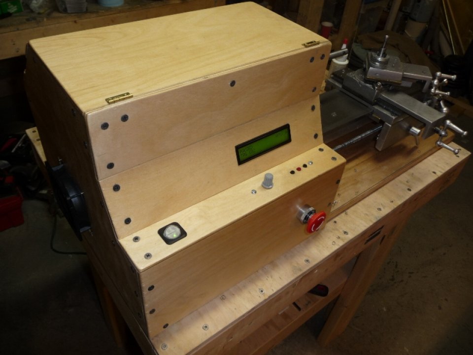
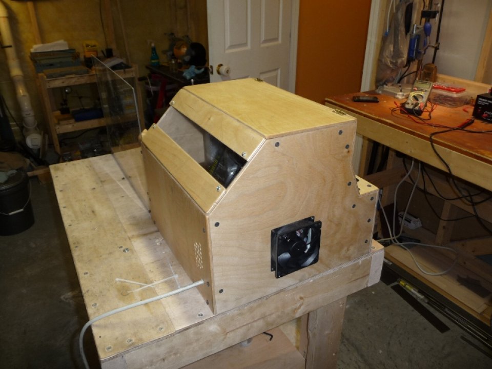
So the first order of business was to design a cover for the lathe. I wanted to enclose all of the electronics, pulleys, belts, etc… and still be able to access everything if need be – especially since I would need to oil the headstock bearings from time to time. I don’t have a sheet metal brake, so I decided to use the leftover 1/8″ Baltic Birch plywood I had lying around from the bed I built for Rowan. The cover was designed to match the form of the headstock, which turned out to be quite nice – especially for the interface buttons / LCD – reminds me of an arcade game. The top of the cover is 2 pieces joined with hinges such that the whole thing could be folded over to provide ample access for making changes without having to take the whole cover off. I also added a ‘viewing window’ to the back which is made from acrylic.
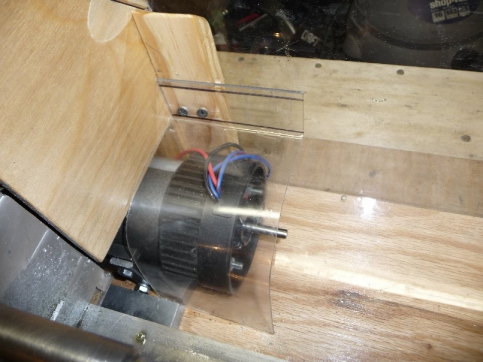
I wanted the lathe to be more portable, so I mounted it to a piece of 3/4″ oak hardwood plywood with a sheet of 1/8″ acrylic in between to provide a sort of drip pan. I also added an acrylic chip shield to the back, and molded acrylic motor cover ( the treadmill motor was too big to fit within the confines of the lathe cover ).
Some photos of the Lathe Cover, Lathe Base, Chip Shield, Motor Cover:

v2 Controller Electronics, Buttons, LCD, etc..
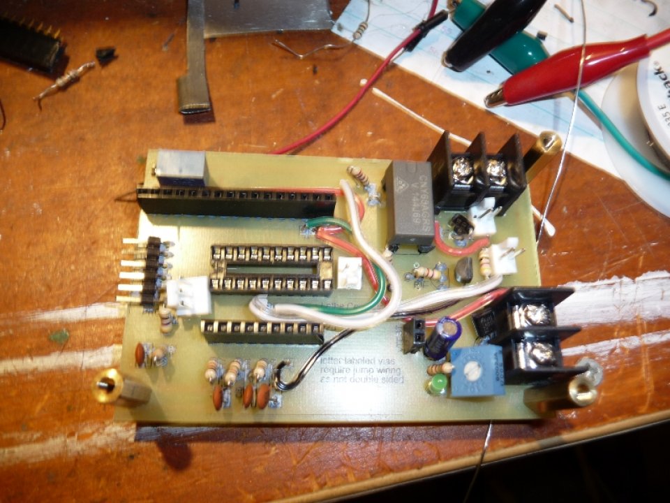
With the new cover completed, I really wanted to finalize the controller board as it seemed to be working well. It was time to move from the perf board + rats nest, to a proper PCB. The new board allows for isolated driving of a 12vdc relay for digitally controlled motor forward / reverse / braking. I also have it setup with a header for I2C if I ever want to expand and add an additional PIC to control a stepper on the leadscrew, or maybe even full CNC someday…
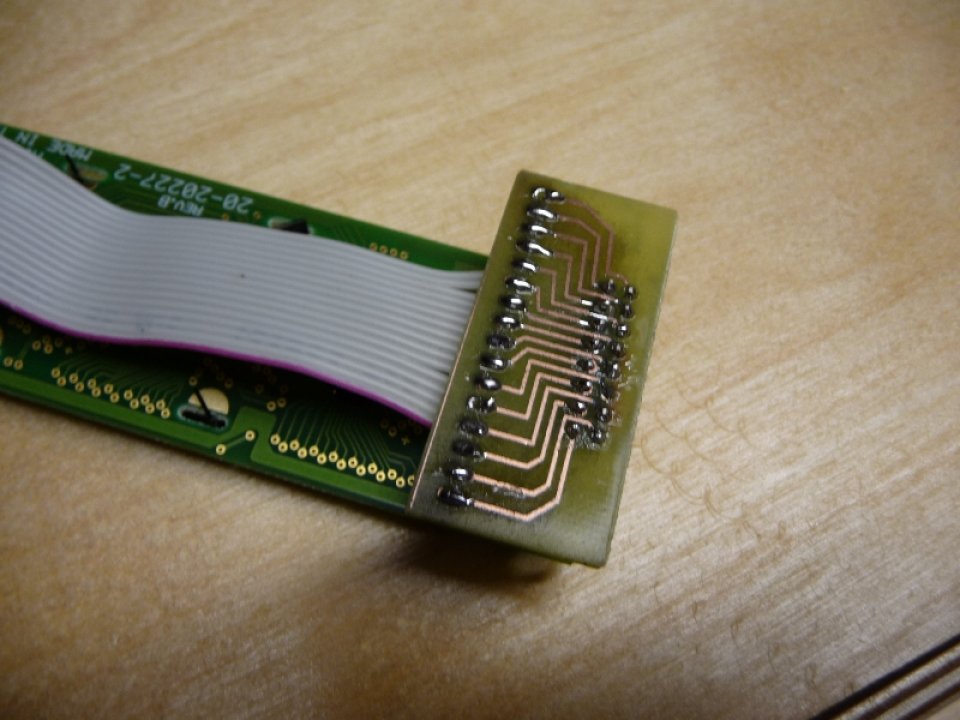
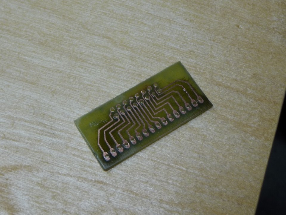
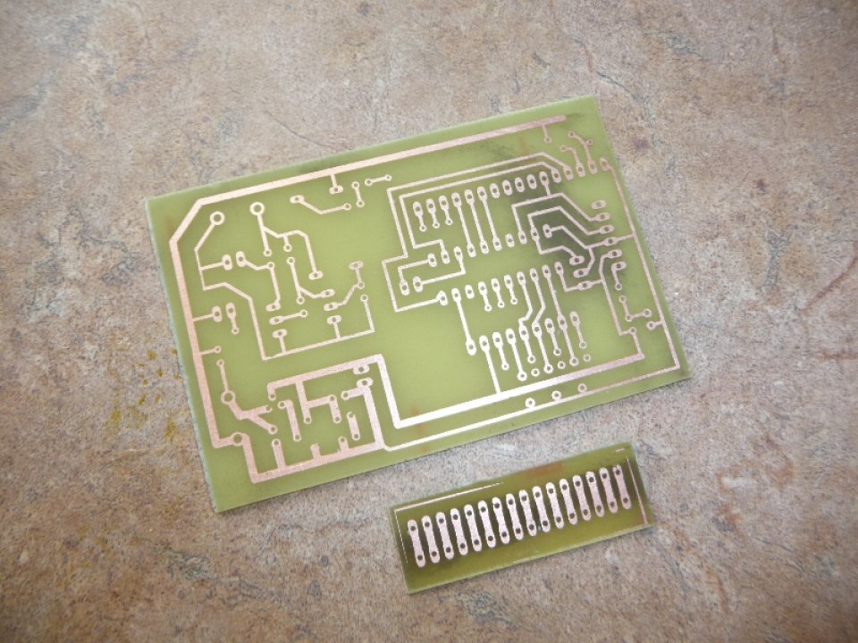
I really wanted to make connecting the buttons, knob and LCD easy and clean. I designed some simple PCBs to provide “ribbon cable to male header” connectivity.
2×8 to 1×16 PCB board ( used for LCD to Ribbon Cable ):

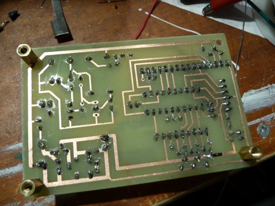
v2 Controller Board + 1×16 to 1×16 ( used for Ribbon Cable to Controller ):
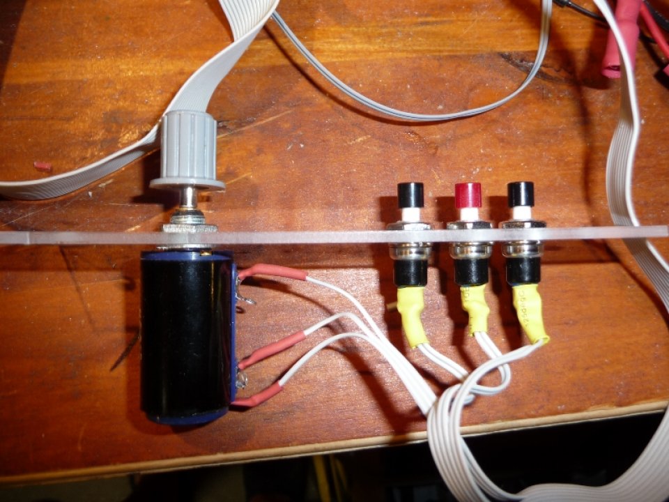
Buttons + Knob mounted to Acrylic for Lathe Cover:
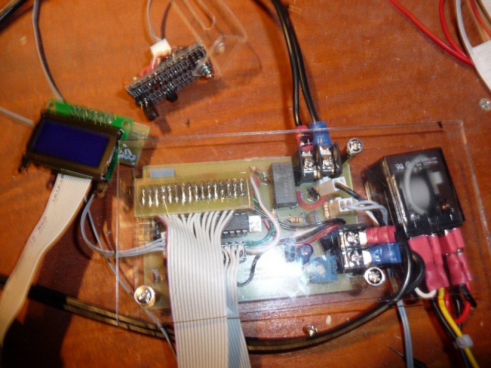
Electronics prior to Mounting in Lathe Cover ( note smaller LCD ):

Mounting + Leadscrew Drive:
Everything came together quite well when mounting the electronics inside the Lathe Cover. Even though I didn’t really plan ahead too much ( hard to do with an hour or two a night ), I did try and take my time and test things out at each step of the way.
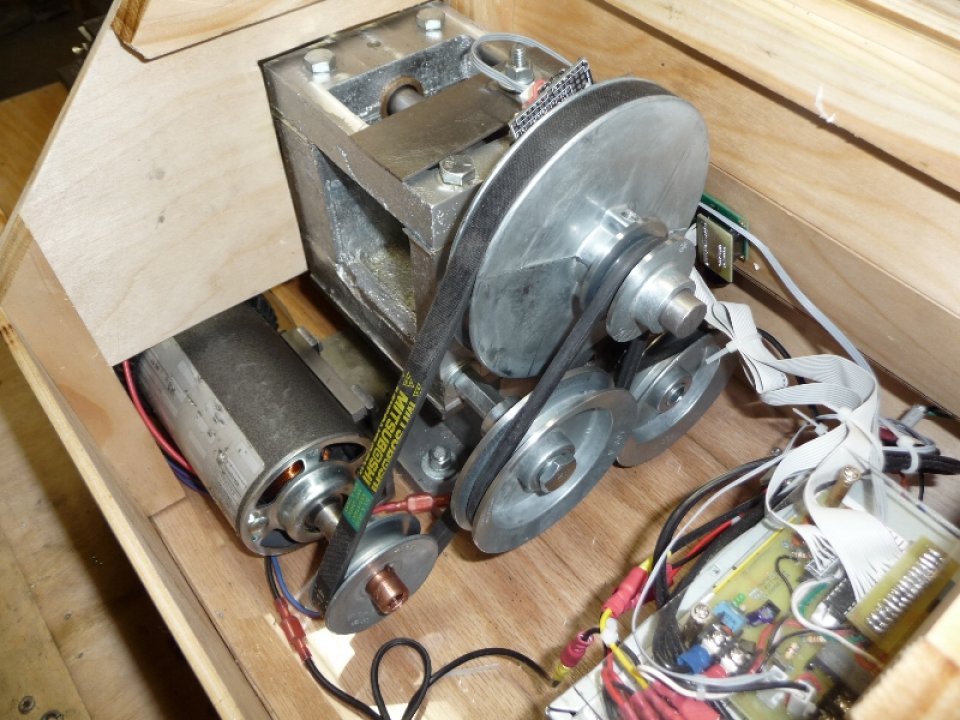
I had initially thought that the leadscrew drive, as specified in the Gingery Lathe Book, would be out of the question due to my outboard pulley / belt getting in the way of axle bolt which would handle one of the reduction pulleys. I was able to extend 1/2″ axle bolt beyond the belt by using a section of 3/8 – 16 stud and a coupling nut. I used the two 4″, and one 2″ die cast pulleys that i had for the reduction setup. Gingery suggests a 1:4 ratio at each stage, but my 4″ die cast pulleys actually have a 3″ diameter that the belt will ride on – so my setup will drive the tool a bit faster than his.
photo of inside of lathe cover, showing leadscrew drive pulleys / belts:
After setting up the leadscrew drive pulleys, I proceeded to use the handwheel and quickly realized it would be impossible to turn the leadscrew by hand with the drive belts engaged. It now makes sense why Gingery says that one of the belts can be removed to use the leadscrew by hand. In the process of trying to turn the leadscrew by hand with the belts on, I ended up unscrewing the leadscrew bearing journals / jam nuts which then required me to take the cover off and fix – a mild pain…
Updated Interface Software + Low RPM Capability
At some point between my last post, and now, it became fairly evident that I would need to start and stop the lathe spindle quite frequently while working on one part. I know it was suggested before, that I would need to do away with the ‘Zero Knob’ then ‘Hold Menu To Start’ safety features I had initially built into the software. My new take on it was to have a ‘Pause’ / ‘Play’ capability which would be set to ‘Paused’ when the system started up. This would allow me to leave the RPM knob dialed in to a typical setting, and would also allow me to leave the machine on – starting and stopping the spindle without having to change the RPM each time ( due to ‘zero knob’ requirement from my old software ).
After my last post ‘First Cutting Operation’, which rendered ok, but less than desirable cutting performance, I dug into the PID control code and found some things that needed to be changed. After some needed tweaks, I was able to get the lathe to make stable / light cuts in steel at 35rpm yay! One other key to the stability was increasing the number of transitions on my encoder wheel from 48 to 96. The QRD1114 that I use to detect the transistions is about maxed out at this point due to it’s unfocused beam. I purchased some newer optical sensors that I’ll be testing out in the future, which hopefully will improve on this even more.
It was becoming a pain to have to re-program the PIC each time I decided on a set of PID constants, or other settings. The PIC18LF14k50 has a built in EEPROM which could be used to store the settings ( even after the power is turned off ). I updated the code such that all interface changeable settings would be stored to the EEPROM.
I added in an additional menu for the ‘Forward / Reverse’ control. The initial setup had a ‘Reverse’ switch which was wired directly to the 12vdc relay. I wanted to have software control over the relay in the event that I ended up adding some steppers to control the leadscrew, or possibly the carriage. The ability to reverse the motor in software would be a requirement if I wanted to fully automate the cutting of threads, or possibly add CNC capabilty someday. I also found that I can use the relay to brake the spindle which is a nice bonus feature.
With the new cover, I decided to switch to a 24×2 LCD screen ( vs. 8×2 ). This definitely gave me some needed freedom with regard to the interface design. I updated the system to display the RPM on the top right of all menus, except the first ( which shows the RPM & RPM Target already ). I also moved the ‘|L’,'|M’,'|R’ button hold indicators to the bottom right.
Finally, on start-up I added a cheesy splash screen that reads ‘Morgan 1 Lathe … v1.0‘. I know it’s still a Gingery, but it’s getting to be a bit unique – might as well put my name on it for fun ![]()
Videos:
Video of me going over the new Lathe Updates + Cutting Demo »
Video of me Cutting Steel at 35, 300, and 830 rpm »
Cheers,
Morgan
Hi Morgan,
found your site through your YouTube videos — very nice work. I’m also starting down the path of a Gingery lathe but I find your drive and drive control system quite different from Uncle Dave’s version. I’m a closet EE but I do a lot more computer work than I do with discrete components. Are there any sites you might recommend that would get me started on building (and understanding) a drive control system like yours? My last bit of discrete circuit design was a transistor amplifier in college.