 It’s always been my goal to be able to produce my own prototypes at home without incurring substantial cost and time ( waiting to receive a part ). I have quite a few manual machine tools, however due to time constraints it is hard to put aside enough time to do the job properly on these machines for anything with substantial complexity. Ideally, I should have attempted to fit up my basement with a small benchtop CNC machine from the start. That being said, I’ve been working on a neat project most this year, and I’m at the point now where I need to design and prototype an enclosure for it. My initial attempts to machine this on my manual milling machine ended up in multiple failures, and I was stuck looking for some alternative means to do it at home. I have the ability to cast items in metal, but even to do that you need the part for the mold, and since this part couldn’t really be made in wood, I was unable to use that process. The parts are to be made in plastic, so metal casting really wouldn’t have been the best option regardless. As I saw it I had a few options, buy, or build, a CNC machine to produce a mold in aluminum for at home injection molding, or produce a part to be used in resin casting. It seemed like that would require more steps than I wanted to take for prototyping a part initially – ideally I want to design the part in CAD, make it, test it, and repeat until I have a usable part. The other option was to build a 3d printer. Up to this point I’ve been a bit skeptical about print quality and strength, however it seems like things have matured to a certain point where you can get good results with a well configured machine. After a bit of research, I was set on building the ‘Box Frame’ version of the RepRap Prusa i3. This post will cover my build of this machine, as well as a few tweaks / modifications I made to it. If you are interested in building this machine yourself, I would recommend checking out the RepRap Prusa i3 Buyer’s Guide for exact dimensions, Bill of Materials, etc… I sourced all my parts on Ebay and Amazon, which required some improvisation on my part to get it to all work together, however there are some great kits out there to be purchased which could get you going right away.
Video:
Making a Box Frame Prusa i3 – 3d Printer
Building The Box Frame
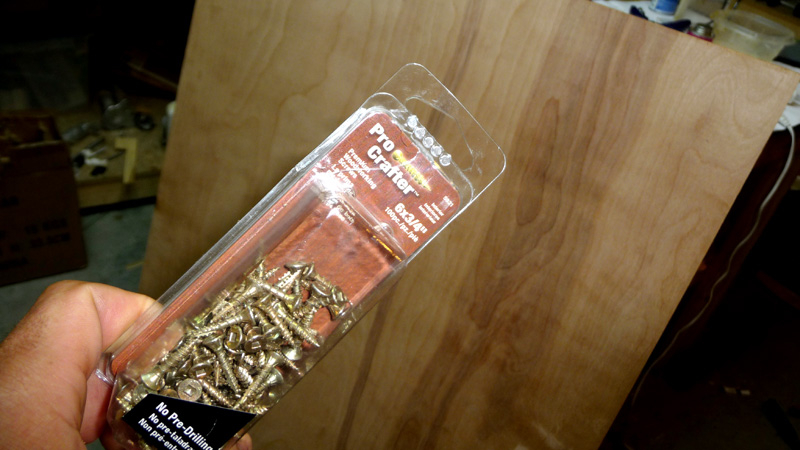
The Box Frame for the i3 is fairly simple, and comes together quickly. It requires only one sheet of 2′ x 4′ plywood, a box of #6-3/4 screws, and paint ( don’t need it but recommended ).
The first order of business to is to cut 4″ wide boards from the sheet of plywood. I don’t have a table saw anymore, so I used my bandsaw. I would recommend doing this on a table saw though if you have one.
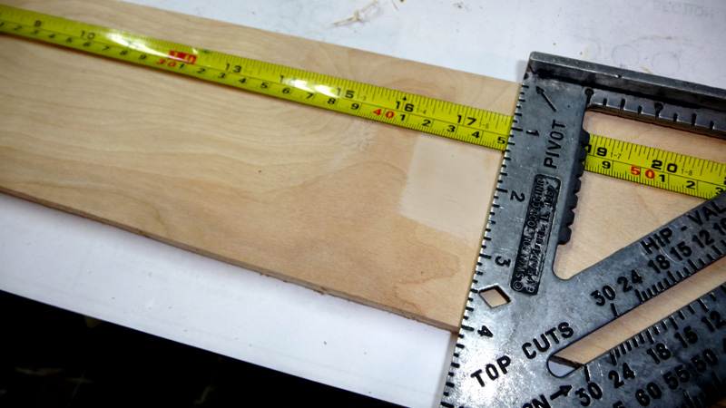
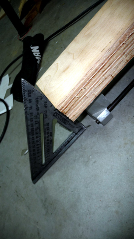
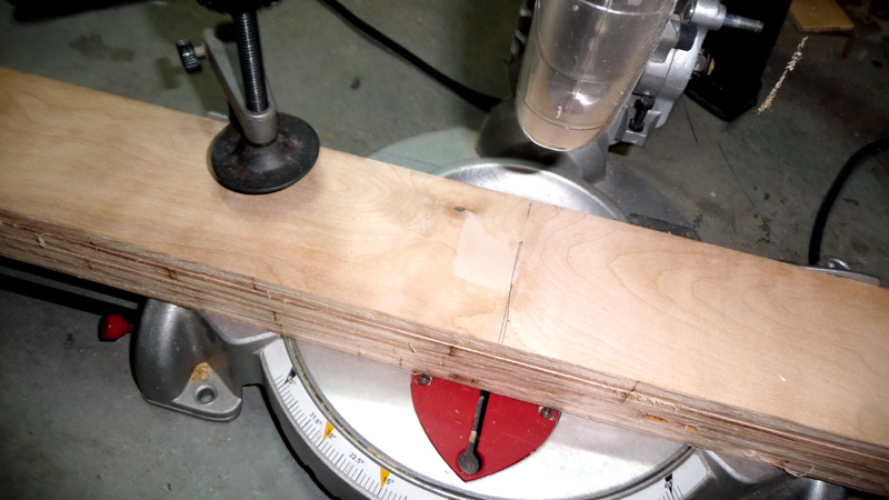
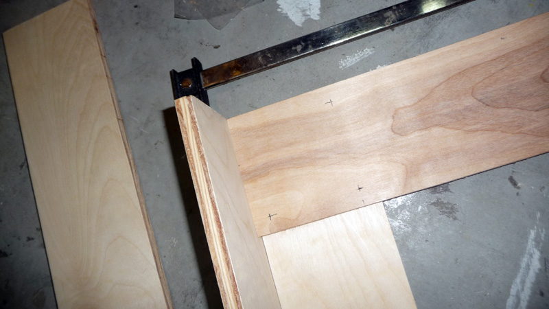
You’ll need 6 x 450mm long boards, so grab a metric capable tape measure and use a square to prep the boards. I was able to cut 4 boards at once with my miter saw, but if you do be sure that the ends all line up ( I used a square for this ).
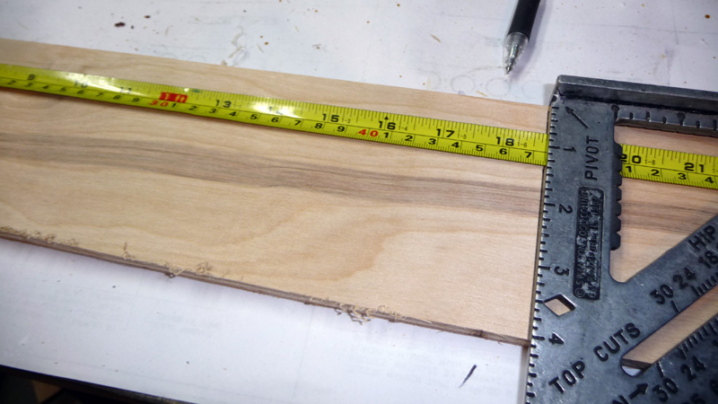
You’ll also need 1 x 475mm long board for the top of the Box. Measure and cut the same as the other boards.

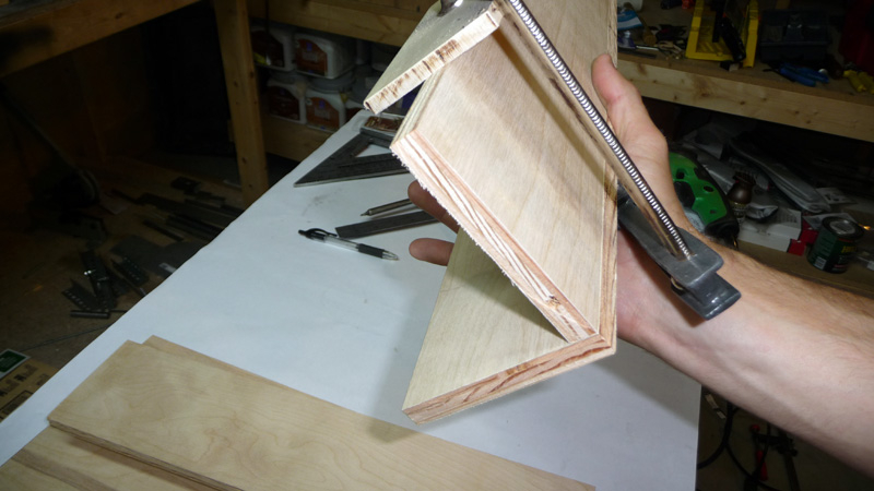
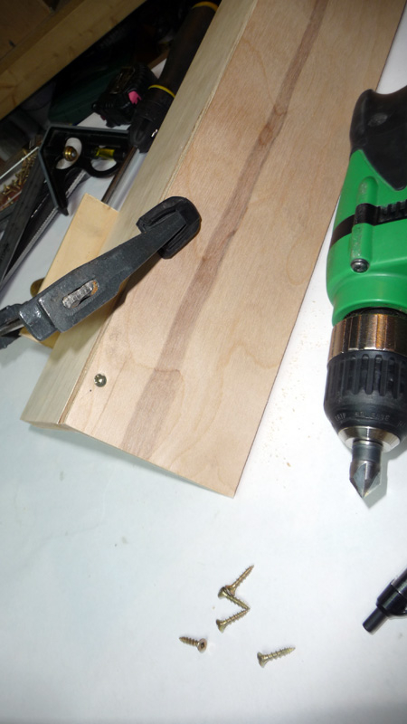
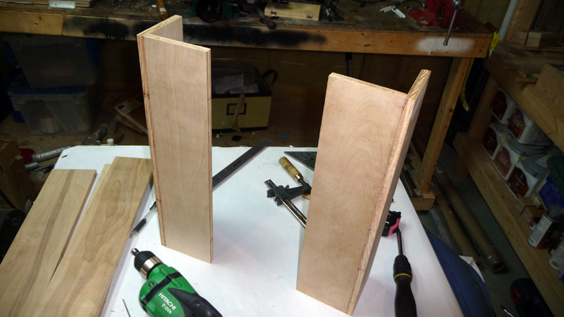
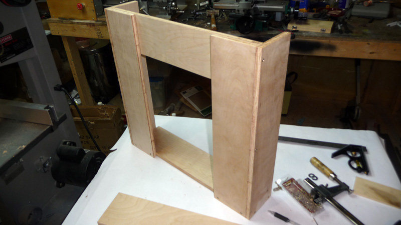
With the boards all cut, it’s time to assemble the Box. Build the two pillars first, and be sure to use a clamp to keep everything lined up and square while you drill, countersink, and screw together the boards.
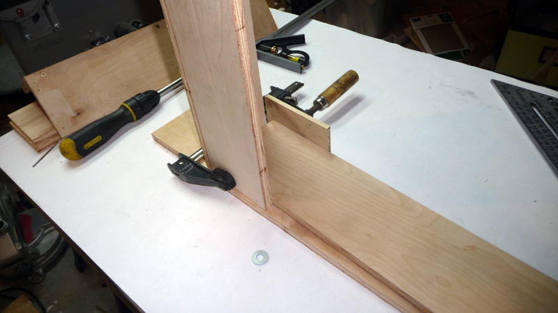
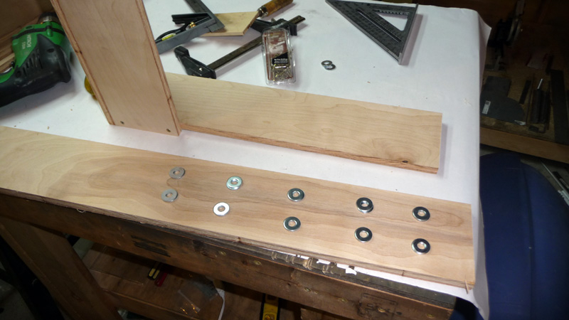
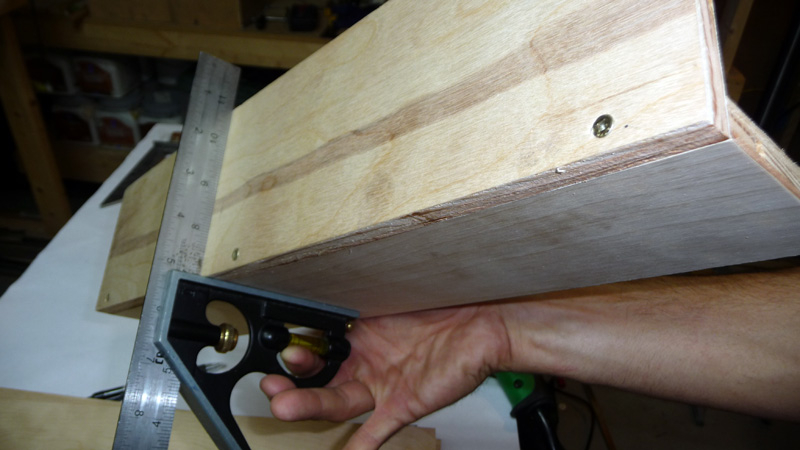
Now it’s time to add the bottom board to the two pillars. This can be a bit tricky, as you need it to be spaced 3mm off the table. There was a recommendation of using two PCBs stacked, however my calipers measured 3.2mm on the ones I had. I eneded up using two 1/4″ washers stacked, as that was pretty much 3mm. Be sure to use your clamp to keep everything just right before you drill and screw in the boards.
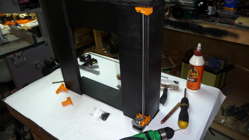
Next the top cross support board is added. You can see from the photos above the mounting points, and the use of a clamp to keep it all together.
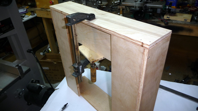
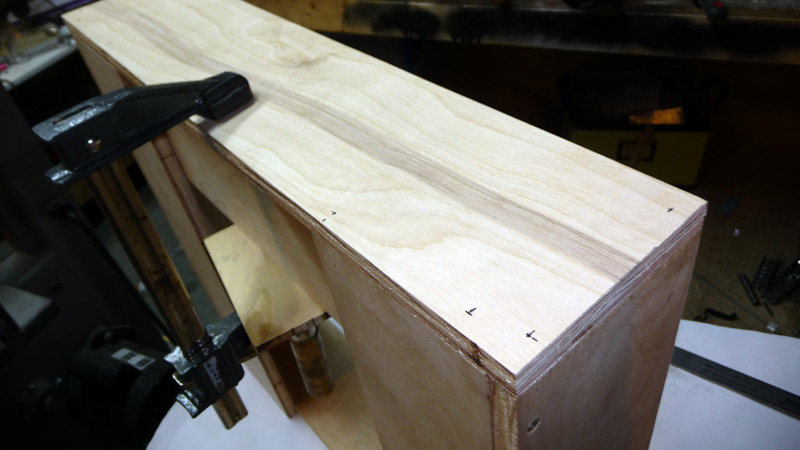

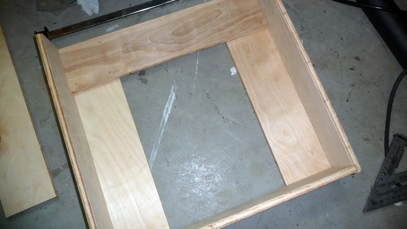
The final part to add to the ‘Box Frame’ was the top piece. I’m using a clamp once again to keep it all lined up. I also ran a bead of wood glue between the top and the rest of it to help keep it all together above and beyond the screws. At this point the original ‘Box Frame’ is done, and ready to be painted.
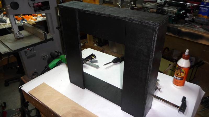
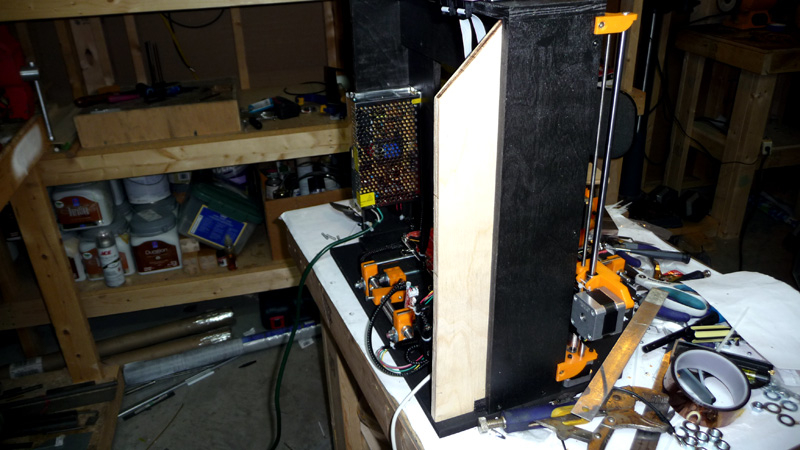
Here is my ‘Box Frame’ painted with Rustoleum Oil Rubbed Bronze spray paint. I had some lying around the house from another project, and it has a bit more luster than a regular flat black. I think it turned out pretty nice.
Mounting the Z-Axis
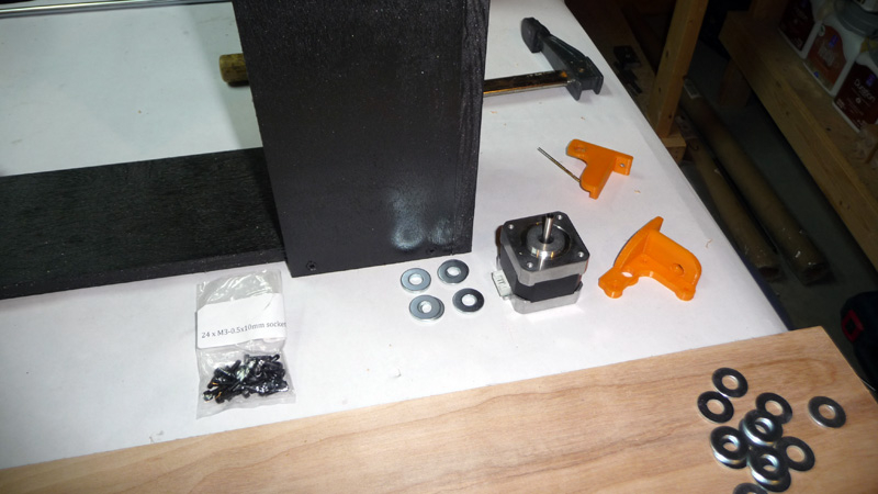
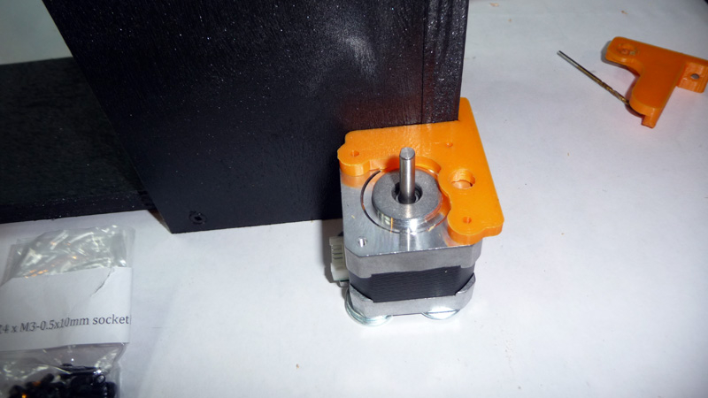
The next step is to attach the z-axis to the ‘Box Frame’. Find the appropriate plastic part from your parts kit, and place a set of 3mm spacers in front of one of the pillars. You’ll place one of your stepper motors on the spacers, and then use that to mount the plastic piece. Keep the stepper there when you drill the hole for the screw that goes into the side of the part. You’ll need to remove the stepper to screw in the front of the plastic piece, so scribe a line at the top of the part on the box frame to ensure it is properly lined up.
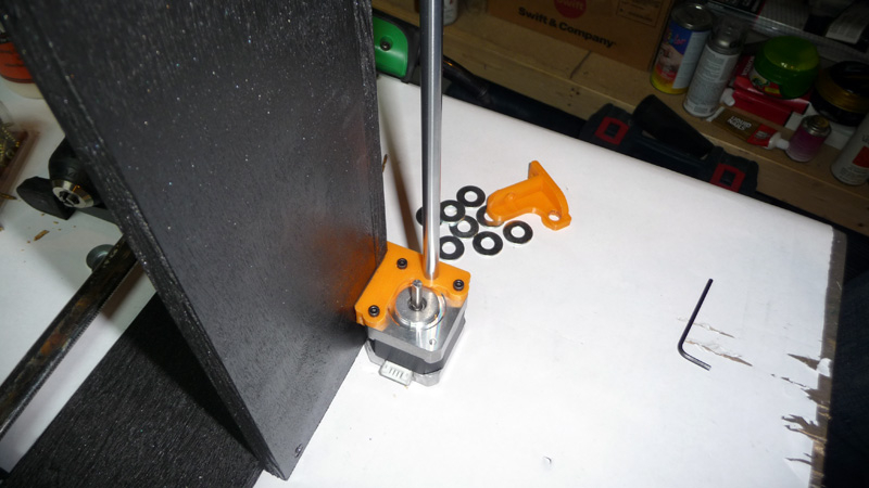
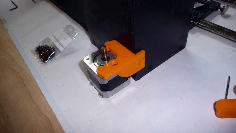
Mount the stepper motor to the plastic piece using M3x10mm bolts. At this point it’s a good ideal to cut all your linear rods down to size if you didn’t buy them pre-cut. Place one of the z-axis rods in the plastic piece, pushing all the way until the rod touches the stepper motor.
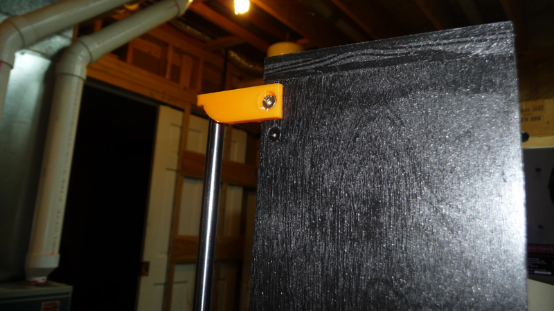
Using the linear rod, you can now accurately mount the top z-axis plastic piece.
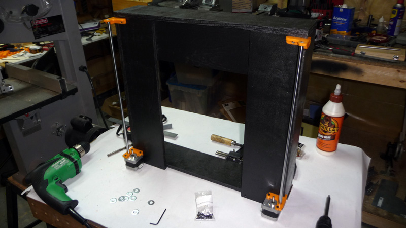
With one side done, repeat on the other to finish up the initial z-axis.
Putting Together The Y-Axis
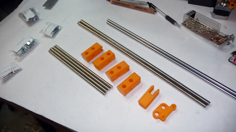
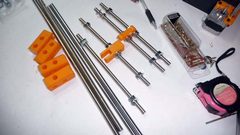

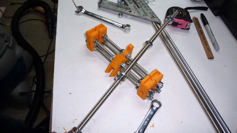
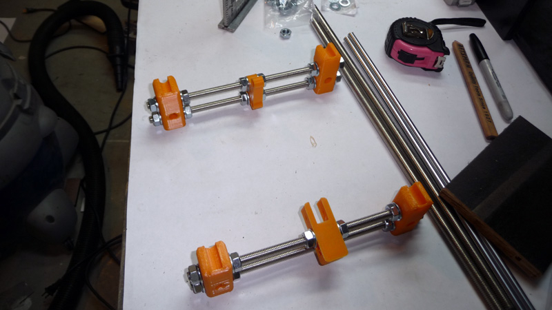
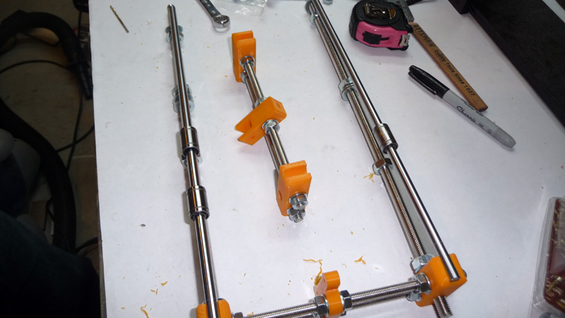
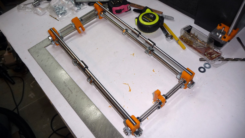
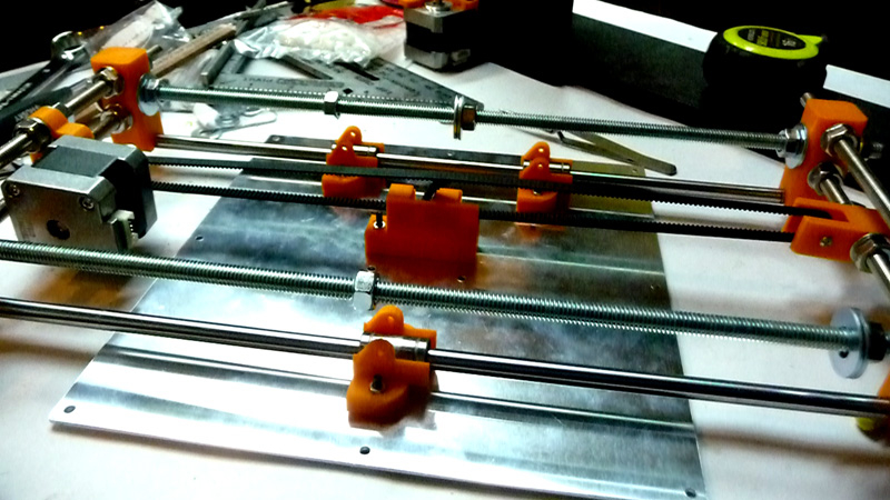
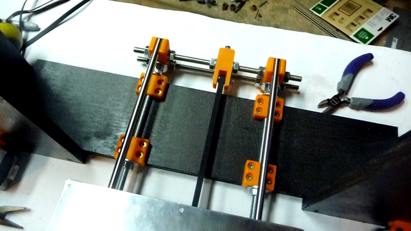
The Y-Axis is a bit tricky to put together, being that you have to adjust 6 threaded rods in order to get a rectangular frame square. I find this is probably the weakest aspect of the RepRap family of printers, and if I was to build a machine of my own making I would probably put the build plate on the z-axis and have it move down ( with gravity ). That being said, start by assembling the two cross sections – one for the belt idler / tensioner and the other for the stepper motor mount. Then proceed to prepare the two threaded rods that run below the linear rods. Put it all together and ensure that the cross sections are equally spaced, and that the whole thing is square. Place the linear rods on the plastic corner pieces, but be sure to slide on your LMUU8 bearings before doing so – two on the right side, one on the left. If I were to do it again, I would probably want to have full support on both sides, 2 linear bearings on each versus one side with just 1 bearing.
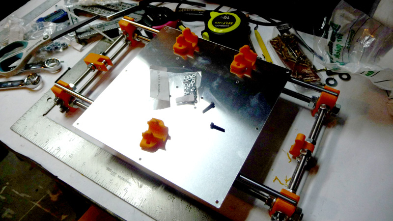
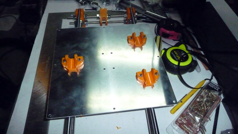

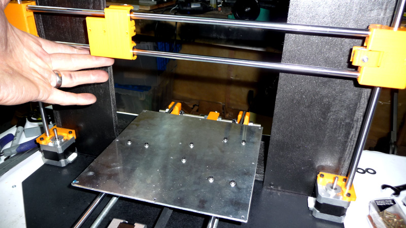
With the Y-Axis frame done, it’s time to mount the bed to it. The original build calls for a piece of plywood, but I opted to buy a pre-drilled aluminum build plate instead. It works quite nice, though the y-axis cross section spacing needed to be adjusted as it was narrower than what I had read online – with the plywood bed it wouldn’t matter so much as you can screw in the mounting pieces anywhere on the plywood.
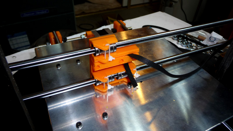
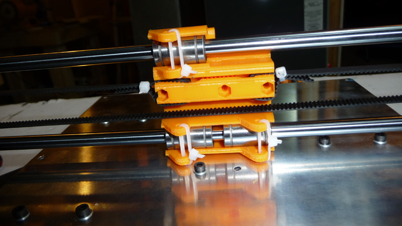
To start mount the plastic pieces for the bed to the bed using M3 bolts. Be sure to use lock washers ( or nyloc nuts ) and some loctite – I found that vibrations in the y-axis at higher speeds caused these to loosen up without lock washers. WIth the plastic pieces mounted, press the bed onto the bearings on the y-axis, and then lock that in using some more M3 bolts and lock washers.

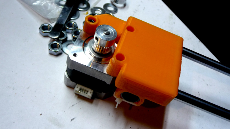
Next mount the y-axis stepper, and then mount the belt holder to the bed. With the belt holder in place, align the y-axis idler and stepper motor pulley such that the belt will run true between them all. It can be a bit tricky getting the belt on the belt holder, so take your time.
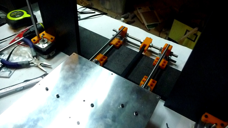
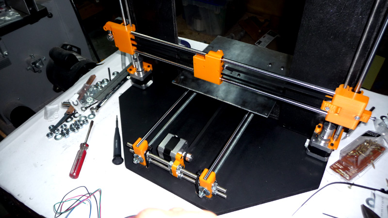
It’s now time to mount the y-axis to the ‘Box Frame’. Center the y-axis on the bottom of the ‘Box Frame’, and be sure that everything is square. Screw down the y-axis to the frame sing the 4 plastic mounts.
Making the ‘Box Frame’ more rigid with a Base Plate
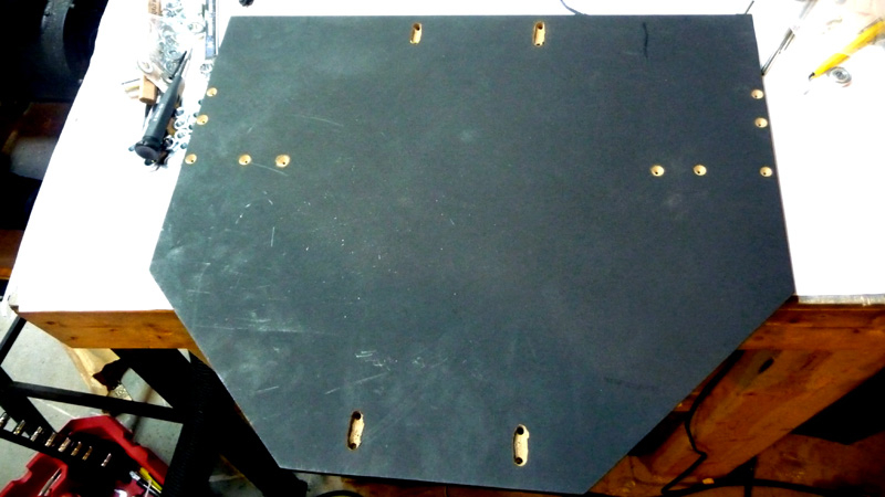
At this point you can get an idea of how rigid the ‘Box Frame’ will be. I was able to move the top of the box just slightly, and it seemed like the footprint of the ‘Box’ was too narrow to really support itself well enough. I decided to make a ‘Base Plate’ for the whole thing out of a piece of MDF I had lying around. The ‘Box Frame’ is mounted to the ‘Base Plate’ underneath the plate using pre-drilled / countersunk holes. I also channeled out 4 locations for zip ties to lock down the y-axis. Once this was done, the whole setup was quite rigid – something I would expect / want from the machine for accurate work.
Putting Together the X-Axis
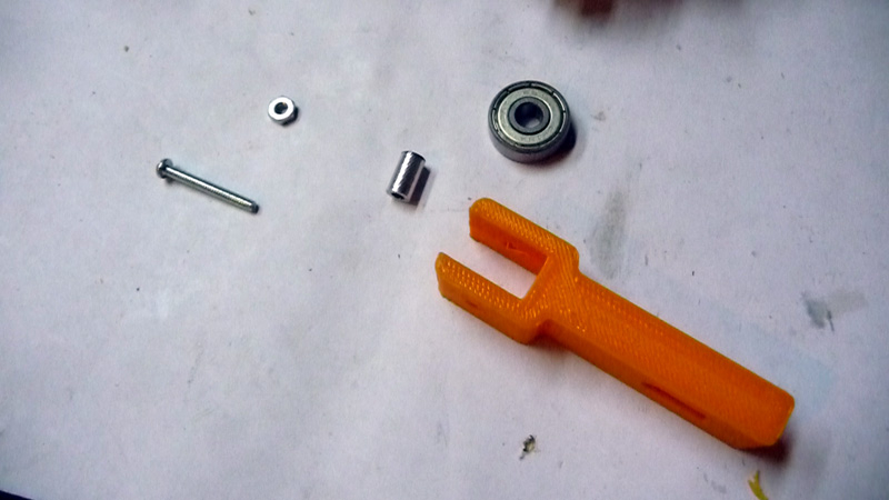
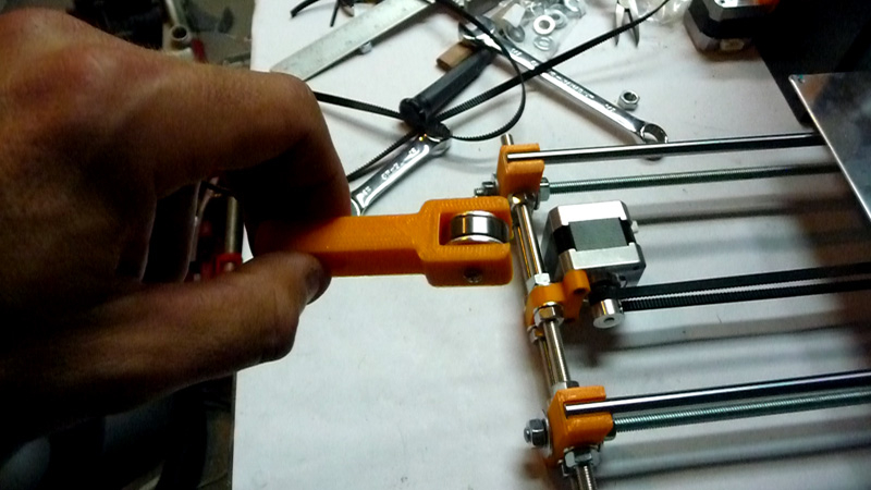
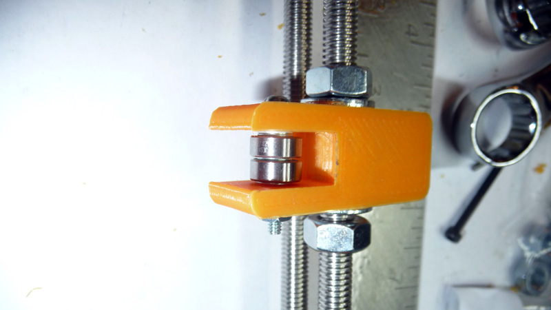
Begin the x-axis by putting together the idler. Being that I sourced my parts on ebay, I ended up with a bearing kit that was for the Rework version of the Prusa i3. That being said, instead of 4×623 bearings I only had 2. Instead of ordering more bearings, I had some 626 bearings lying around which I was able to use with a little work. I turned down a piece of 1/4″ aluminum round stock into a spacer for the bearing, such that I could still use an M3 bolt as an axle. I had some spacers for 608 bearings lying around from some roller blades I had taken apart, and the ends of those fit perfectly inside a 1/4″ washer. The inside diameter of those also fit perfectly over the custom spacer I turned down on my lathe, and thus I was able to produce an idler that would work using 626 bearings ( the 1/4″ washers on each side of the bearing help fill the game, in the event that the belt might walk off the bearing and get stuck, etc.. ).
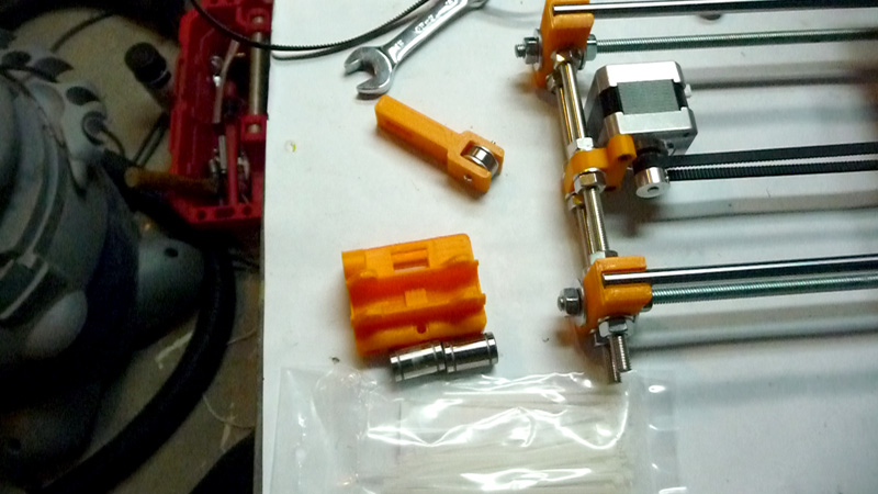
Next add all the LMUU8 bearings to the x-axis plastic pieces. Cut out the extra plastic on the idler piece where the idler goes, and then attach the idler with M4 bolts / nuts. You’ll need to place the M5 nuts in the traps for the z-axis threaded rod, and then slide on the x-axis linear rods.
Lift the z-axis linear rods off the bottom mounts in order to slide the x-axis assembly up on the z-axis rods. Once the x-axis is on the z-axis rods, push the z-axis rods back down into the bottom z-axis mounts as before. Test both the z-axis and x-axis movement, making sure everything is smooth and not binding at all.
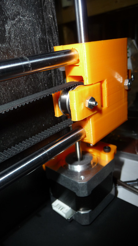
With the x-axis on the z-axis, you can now attach the x-axis belt. Similar to the y-axis however the holding part is a bit trickier to work with. If you have a mechanism to tension the belt on your idler, let it out all the way such that you can let the belt be a bit loose while attaching it to the holder. When done tighten the bolt on tensioner to tighten the belt.
It’s now time to add the 5mm threaded rods to the z-axis. I’m using flexible couplings versus the tubing in the original build. Thread down the rods, and then use the set screw on the coupling to secure the stepper to the rod.
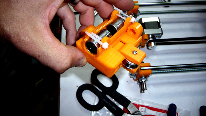
Putting together the Wade’s Extruder

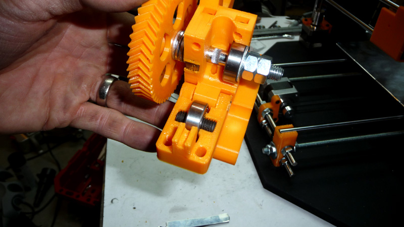

With the x-axis all set on the z-axis, it’s time to put together the extruder. The most critical part of the wade’s is getting the hobbed bolt lined up with the hole for the filament. In my case, with my particular hobbed bolt, I needed to use quite a few washers between the big herringbone gear and the extruder body. If you purchased a bearing kit for your machine, be sure that it has 3 608 bearings for the Wade’s Extruder.
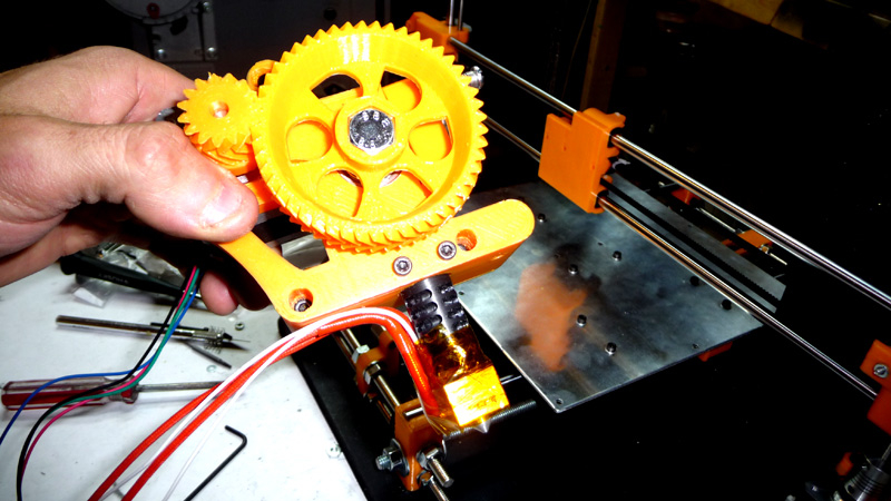
With the cold end assembled, attach the hot end ( in my case a JHead MK V – 0.4mm nozzle for 1.75mm filament ) to the extruder. The Wade’s Extruder has two set screw holes that can be used to mount the JHead, however this setup failed fairly quickly for me when printing ABS. I ended up building a mounting plate out of some 1/8″ aluminum bar stock that I had lying around. If I was to do it again, I would have added the aluminum mounting plate to my list of things to buy for the machine.
Attach the extruder to the x-axis.
Finishing the Build
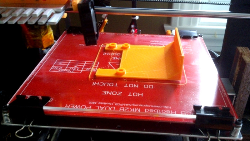
Sorry, at this point the details get a bit thin. Basically the next few steps involve adding the end stops, putting together the electronics ( in my case RAMPS 1.4, an Arduino, 12V 30A power supply, etc… ) and using some type of cable wrap to make it look nice and neat. I also attached a heated bed to my build plate using M3 bolts, springs and nyloc washers. On top of the bed is a sheet of glass attached with binder clips. Each of the pololu drivers need to be adjust to 0.4V to start as well.

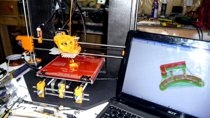
So with the electronics all set, I was able to load the Marlin firmware onto the Arduino, and get it to start printing. One thing to note, my printer was working extremely erratically with the firmware from the CD that was included with the RAMPS board I bought on ebay – I would recommend just downloading a fresh copy of Marlin from github – unless you bought your printer as a full kit of course…
The first few test prints ended up failing 40-50% through. The filament would jam up at the idler causing the print to fail. The first attempt to fix this was to reduce the size of the Wade’s Extruder filament feed hole as my JHead was for 1.75mm and I’m sure the Wade’s I have was for 3mm filament. I used the ink tube from a pen to fix this issue ( suprisingly the fit is perfect ). The fix didn’t really solve the problem, though the jam had different characteristics. I noticed that the aluminum mounting plate was getting a bit hot, and that gave me the idea that the PEEK was getting too hot and some of the molten plastic was flowing up and solidifying causing the jam. I ended up added some heat sinks from a PC power supply I had lying around. Even though in hindsight, this was not the reason for the jamming, it did help get through some prints without issue.
When I started to run the machine faster ( 75mm/s and higher ) I found that I was running into the ‘jamming’ issue again. Taking off the JHead I found the PTFE liner was pushed up, and there was solidified molten plastic in part of the PEEK. Researching online it appeared that a setscrew was required to hold the PTFE liner in place, which was the issue. My particular JHead came with a brass nozzle ( and blue filament locking mechanism of some sort ). That was removed to fit the JHead into the Wade’s, however it left the PTFE free to move in the PEEK. I ended up cutting the threads off the brass nozzle, tapping the small hole in it partially such that I could use a #6 machine screw to screw it back into the PEEK ( as there was nothing else to hold onto once the threads were off the nut ). Once I got the whole thing back up and running, oh my, it worked perfectly at high speeds.
I also quickly got tired of trying to get the Kapton tape onto the glass without bubbles. I ended up buying some Aquanet Hairspray, and that works perfectly without any Kapton at all.
Printing a 40mm Print Fan Holder
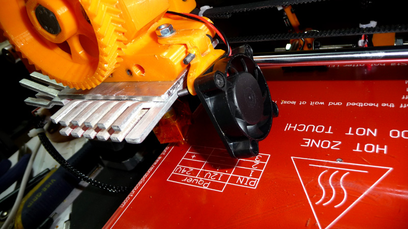
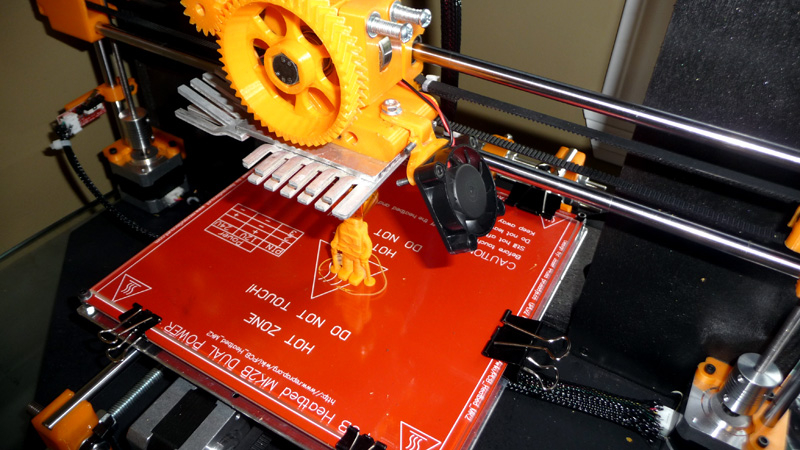
The next thing to add to the machine was the 40mm fan that I had purchased. It seemed like this would be an essential addition for prints that had bridging, etc…
Making the ‘Box Frame’ even more rigid with side supports
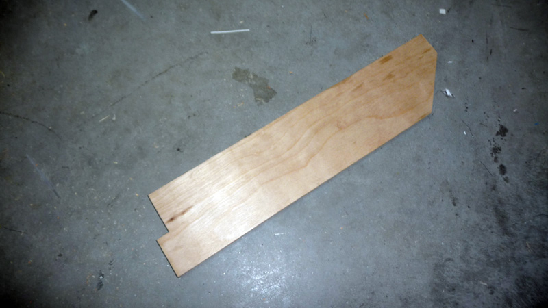

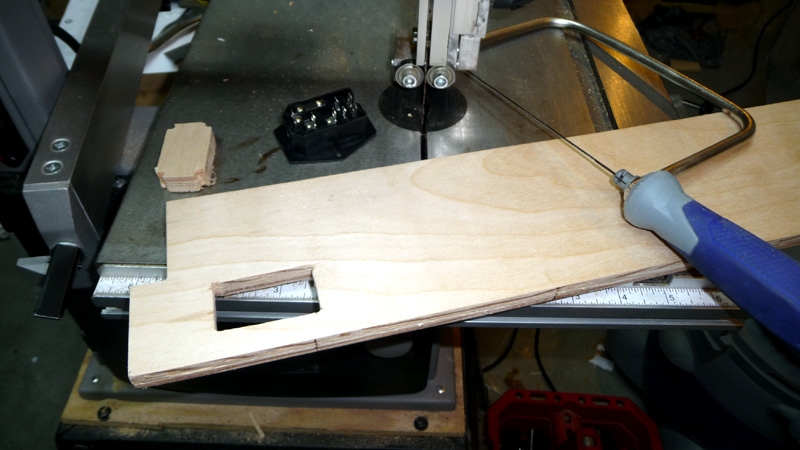
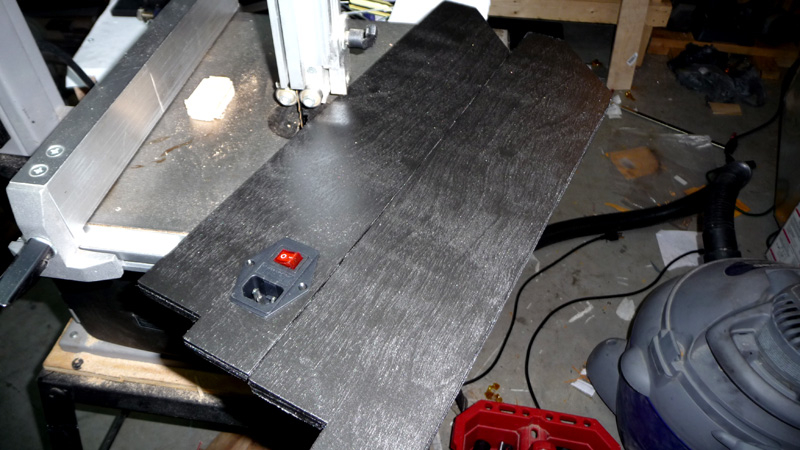
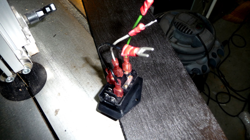
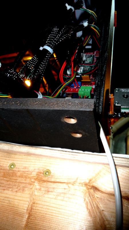
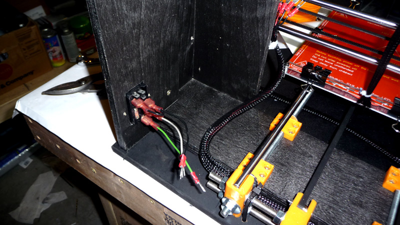
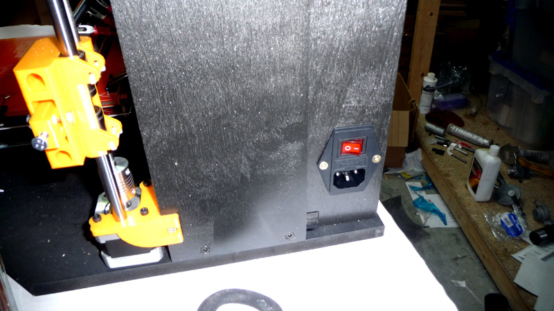
At this point I was ready to add some final touches to the machine. It seemed like even with the ‘Base Plate’ the ‘Box Frame’ could be more rigid. I decided to add two additional support pieces, with one acting as a mounting point for a power connector / switch / fuse. The support pieces are attached to the inside of the ‘Box Frame’ and also up from underneath the ‘Base Plate’.
Adding a Basic Spool Holder
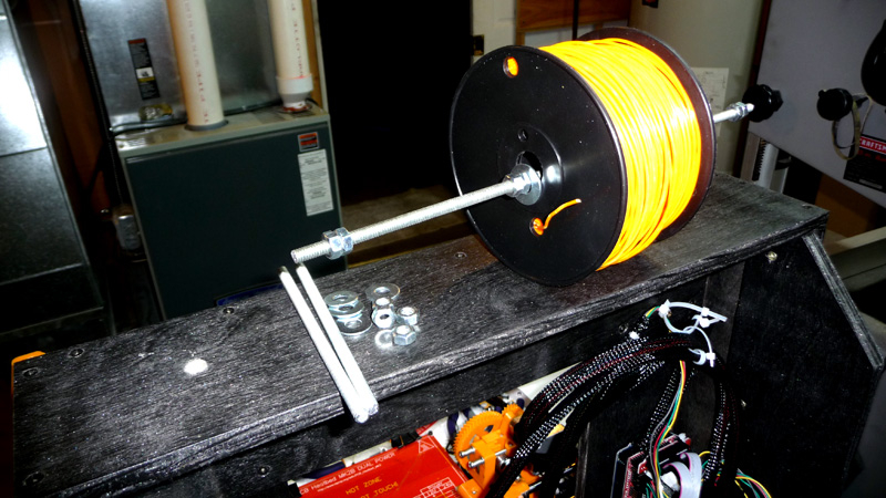
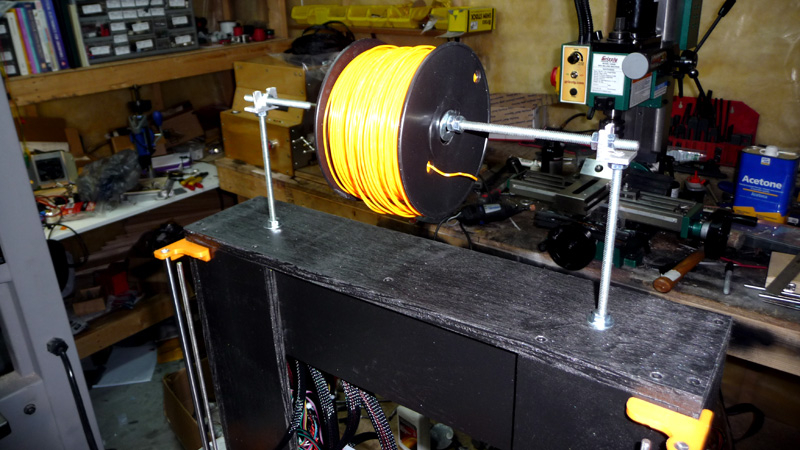
At this point I was ready to add a basic spool holder to the Prusa i3. Once you start printing it will quickly become apparent that a spool holder is an essential part of the machine. I had some 1/4″ threaded rod lying around that I used for a very basic spool holder. Instead of printing the corners, I used some scrap angle aluminum I had lying around – what’s the point of printing something for a half an hour that you can make in 2 minutes right? haha.
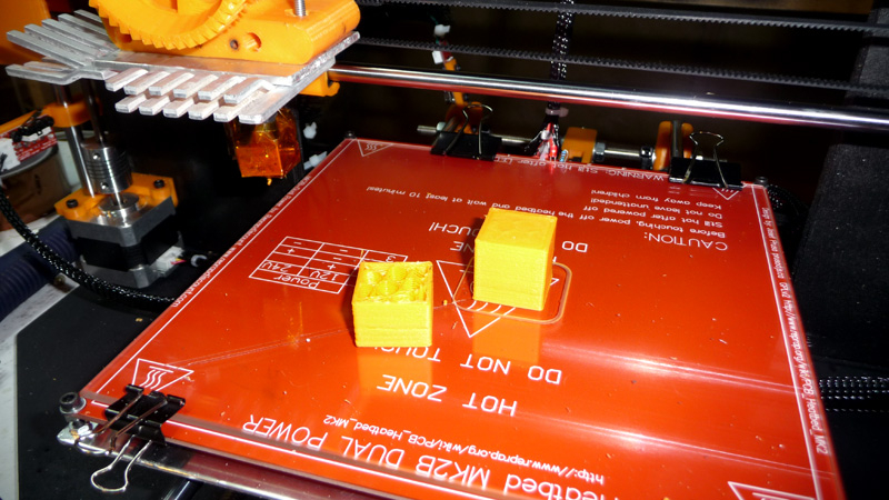
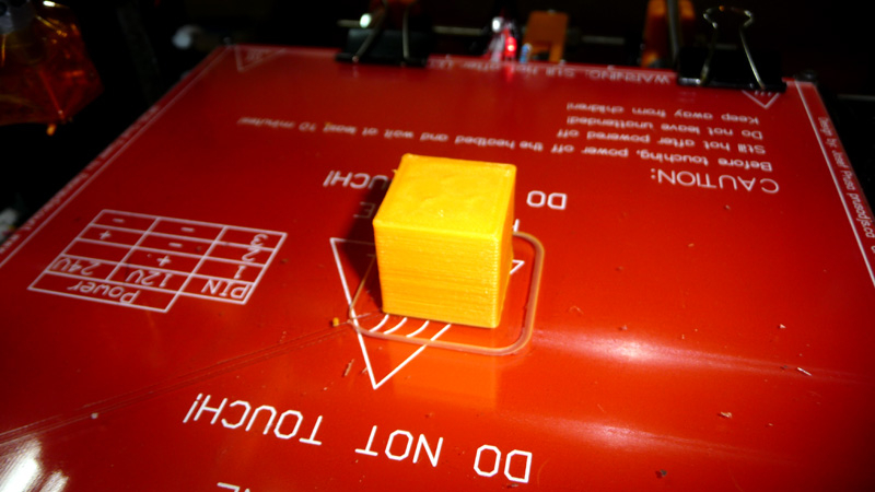
Some More Test Prints / Results
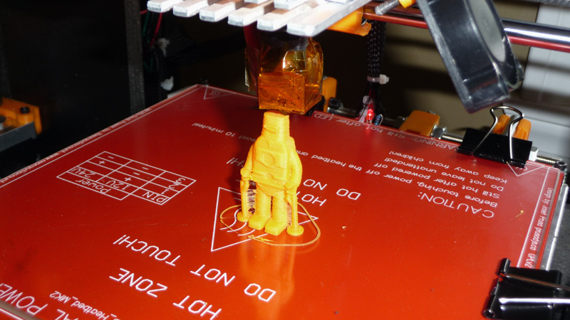
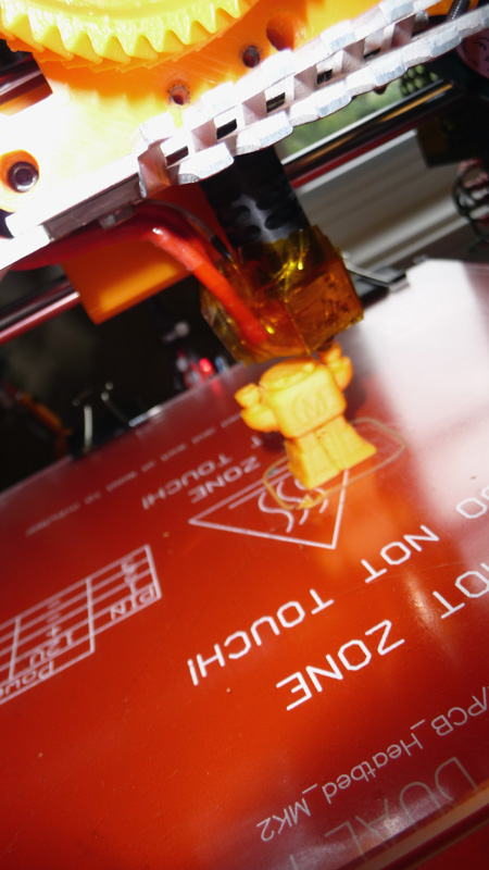
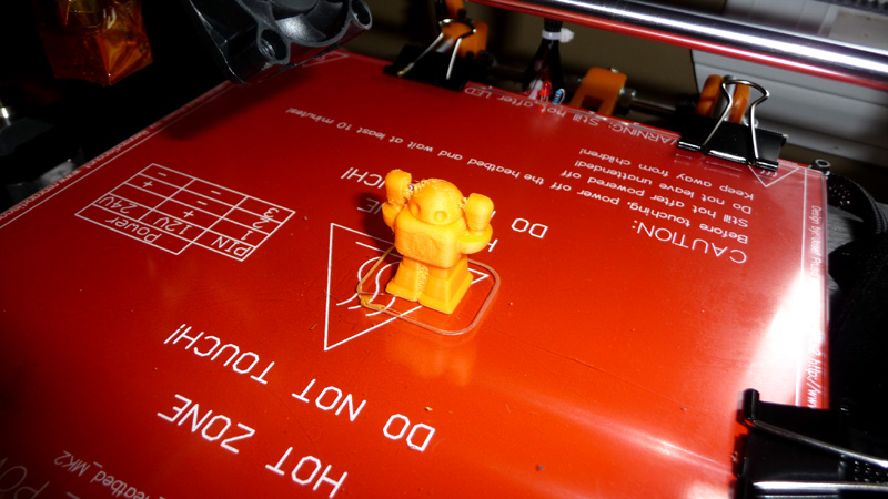
The above photos show the print quality I was getting at this point in time, not too bad.
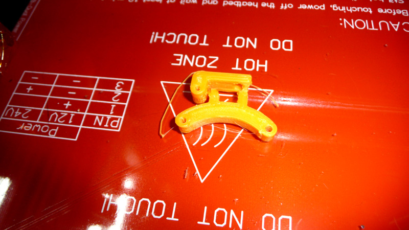
Mounting the Graphics LCD for my Prusa i3
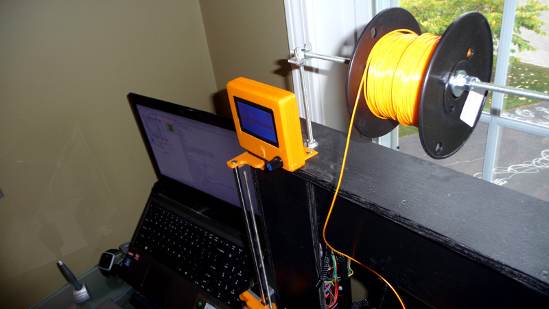
One of the final items on my list was to mount the graphic LCD that I ordered for my RepRap. It allows the machine to operate without a computer via it’s built in sdcard slot. I ended up finding a case to print from Thingiverse, though I designed my own mount for it which you can see in the photos. I have a new design that I need to print, as this one had a bit too much flex ( so I won’t be putting it online for download yet ).
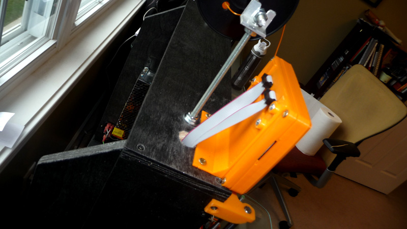
Fixing the noise in the Y-Axis

My printer purrs at 50mm/s, though I do enjoy printing at 100mm/s to get something printed quickly. I found that at those speeds there would be quite a bit of noise when the y-axis would make quick movements back and forth. Nothing appeared to be vibrating, though when I lightly pressed down on the aluminum bed, I found that the noise would go away. I ended up designing a quick prototype dampener that sites on the left side, in line with the extruder ( such that you don’t have to worry about the bed leveling screws running into it ). Tow pieces of wood are screwed together to form an L shape, and at the top of that is a 1/4″ wide U channel. A piece of angle aluminum was cut to size, and some felt I purchased at a marine store was glued to the underside of that. Using 1/4″ bolt, nut and lock washer the angle aluminum can ride up and down the mount allowing you to bring the felt into contact with the aluminum bed ( between that and the heated bed ). With it just touching the bed, all the noise has pretty much gone away at high speeds. I may end up designing a printed version of this and putting it online at some point.
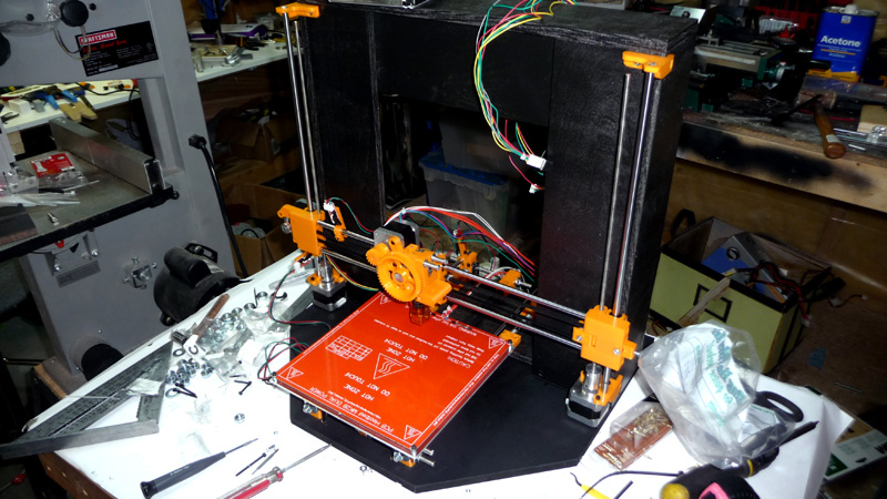
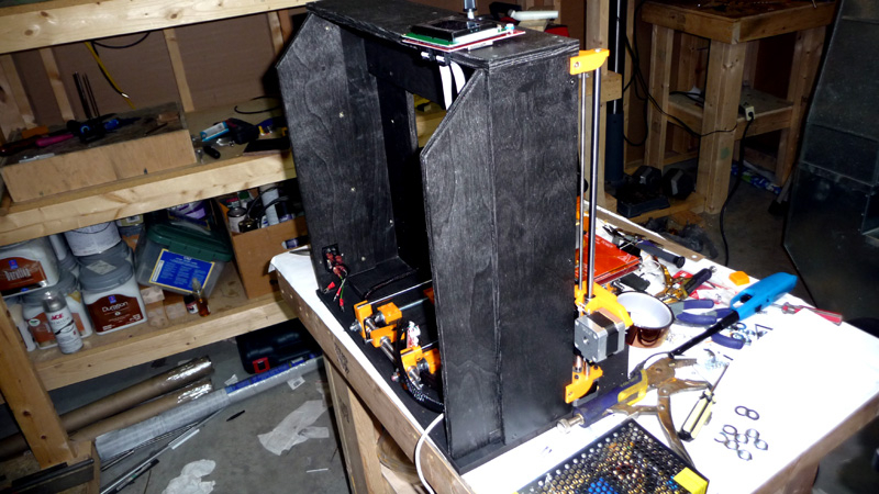
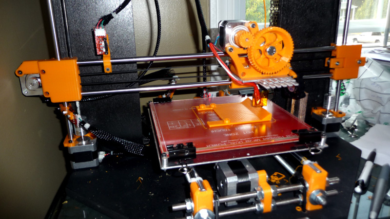
The Printer As Of Now
Well everything is all set, and I’m pretty much ready to print the parts I need. Overall I’m quite happy with the machine, and it prints well. I’m sure I’ll keep working on the machine as I need to, and will post updates accordingly. I’d like to give PLA a try, maybe get dual extruders going, and try out acetone vapor to smooth out some of the prints, etc…
Happy Printing,
Cheers,
Morgan
Impressive work as usual, Morgan. Thanks for sharing!
Hi Morgan, Like yourself, I am very much a prototyping 3D printer user. i designed and built mine a couple of years ago and yes, its invaluable for ‘getting it right” in plastic first before committing to metal. BTW, have you registered on reprap.org’s forum?
Regards,
Alan long (waitaki)
Hey Alan,
Thanks for the post! Sounds like you may have some metal casting experience? If so, have you tried using a PLA print in investment casting? I don’t have anything that I need in metal at the moment, but would be fantastic if I could use a PLA print as a replacement for foam in lost foam casting.
At this point I’m not on the reprap forum, though I should definitely setup an account there.
Cheers,
Morgan
Hi Morgan,
Long time since I played around with metal casting but using PLA for casting has been talked about on the Reprap forum though not sure if anyone has tried it yet – I would be interested to know myself.
Firecast resin on SLA printers has been mentioned if you wanna check that out.
http://madesolid.com/fire-cast-resin.html
Cheers,
Al
Nice build and thanks for documenting it,
I am building a Box Frame Prusa i3 “classic” very similar to yours, I am using the parts off of Joseph Prusa’s github site and printed all of my parts (I already own a printrbot plus). I used your idea to build a base using some 3/8 plywood too. I just finished 90% of my mechanical assembly and am not happy with the play in my aluminum plate after I just wire tied my plate to the LM8UU bearings. I see from your pictures you have some printed pieces that mount the plate to the bearings, I can’t seem to find ones like yours anywhere after searching thingiverse and a few other 3d sharing sites. Can you share where you found those parts?
Hey Terry,
Thanks for the comment, it’s appreciated. For the parts I used in my printer checkout this page ( http://johnridley.blogspot.com/2010/10/building-prusa-i3-printer-pictorial.html ) they are the ‘Linear Bearing Holders’. I would also recommend replacing all of your zip ties with machine screws and nyloc nuts ( or nuts and lock washers ). I learned the hard way, and am now getting much better results without them. I also used some loctite as well for added security.
Also, I’m going to be putting up another post / video soon of some new updates I made. Basically I was still getting some curling / warping in the corners with ABS and larger parts. Really it’s essential to build an enclosure for the machine, and also to warm it up before printing.
Cheers,
Morgan
Thanks for the link that is exactly what I was looking for. I have been down a similar journey with my printrbot plus and spent a lot of time making it more stable by removing zip ties and doing other modifications so I kind of know exactly what things will likely cause problems, that is why I was seeking that particular part out. I also built an enclosure out of plexiglass panels for that printer and plan to do the same for the prusa i3, it significantly improved my print quality with larger volume ABS parts. I will be very interested in seeing what you came up with for an enclosure.
Hey Morgan, I’m building pretty much exactly what you have. I have been looking for a printed parts kit for the box style frame and really can’t find anything other than some place from Spain on ebay. Did you have your parts sourced from a local place or did you order them off ebay? If so can you share the link to where you bought them?
Hey Spencer,
I purchased my plaatic parts from the below ebay item:
http://www.ebay.com/itm/Reprap-Prusa-Mendel-i3-Rework-Printed-Parts-KIT-DEEP-BLUE-3D-Printer-/231218257888?pt=LH_DefaultDomain_0&hash=item35d5ae9fe0
if you have access to a printer they most resemble these parts:
http://www.homemetalshopclub.org/projects/toolpost/toolpost.html
Cheers,
Morgan
Do you know where you got the stls or atleast the x carriage for the printer I have been trying to make a box frame i3 for a while but my x carriage doesn’t line up with any extruder
Hey Sean,
I purchased my parts as a kit on ebay, though what I got most closely resembles the parts here:
http://www.homemetalshopclub.org/projects/toolpost/toolpost.html
Cheers,
Morgan
Thank you sir, this post really helped me build a 3d printer on my own. Hope to build many more in the future.