A new tool post was well overdue, the DIY lawn mower axle lantern style had served it’s purpose. I really wanted to be able to get the tool bit as close to the chuck as possible, with little to no overhang. I happened upon some plans from George Carlson for a ‘Norman Patent Style’ Tool Post, which seemed like an ideal built for my lathe.
Step by Step Video of Making a ‘Norman Patent Style’ Quick Change Tool Post:
How To Make a Quick Change Tool Post Video
Photos of the finished Quick Change Tool Post:

 The Tool Post build is fairly straight forward – turn down the post, and then make the tool holder(s). The main challenge being turning down a piece of 2″ round 1018 stock to 1″ in diameter, and also boring out the 1″ diameter tool holder mounting hole. It was the perfect opportunity to put my Gingery Style Lathe to the test.
The Tool Post:
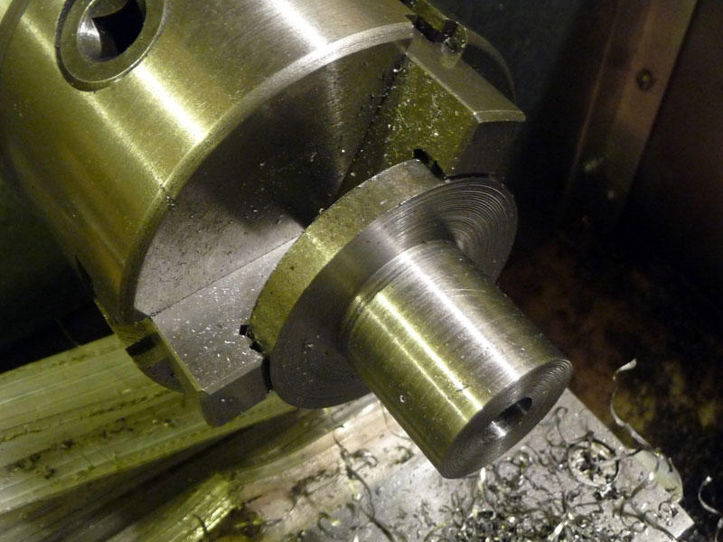 To start, mount the 2″ round stock on the lathe, and center drill the free end. Using that center drilled hole, support the free end of the stock with the the tailstock center. Turn down the post to 1″ in diameter, leaving about 1/4″ of the stock at 2″ for the tool post’s base.
Remove the tailstock center, and face off the end of the tool post. It’s now time to drill the tool post mounting hole on the lathe. You can make it whatever size you need for your particular lathe, though for me it will be 3/8″.
The Tool Holder:
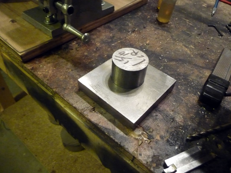
Cut a slight larger than 2″ length of 3/4″x2″ 1018 bar stock. I sure wish I had a horizontal bandsaw at this point, maybe someday. Once cut I proceeded to clean things up on my milling machine making the block 2″ square. If you don’t have a mill, you can get the job done with some elbow grease and a file.
Locate the holder’s lockdown hole 0.35″ in from the end, and 0.375″ up from the bottom. Drill a 1/4″ hole 1″ deep, and then drill all the way through with a #7 drill to be tapped later to 1/4″-20. Counterbore the hole 1/4″ with a 3/8″ endmill if you have one – you don’t need to use an allen head socket screw, a 1/4″ hex bolt works perfectly fine and is what I ended up using. Even with the counter bored hole, I found that the allen head screw would still bind prior to me being able to fully lock down the holder on the post.
Tool Holder Boring Setup Photos:
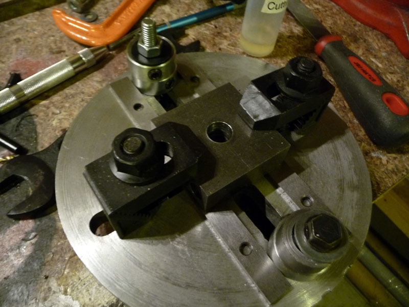
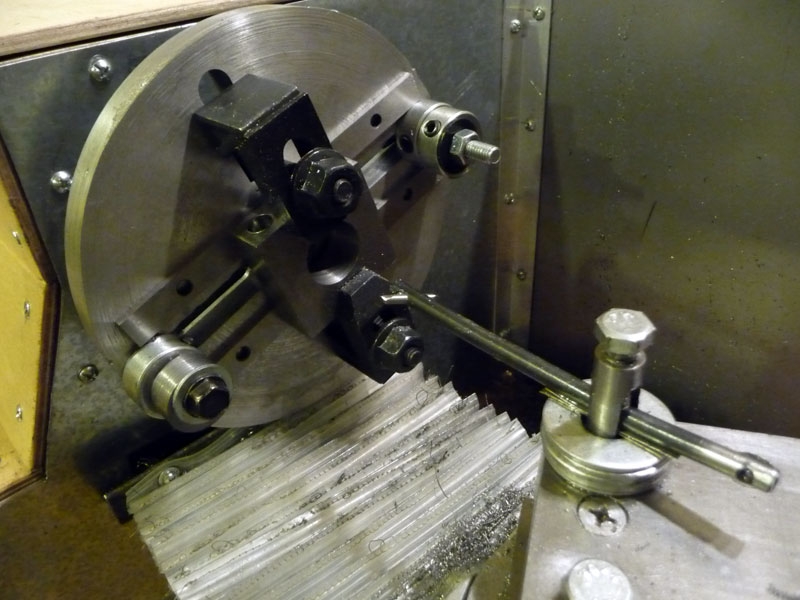
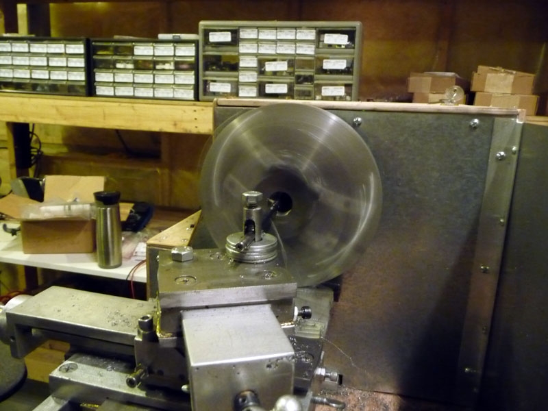
Locate the center of the 2″ square block, and step drill that up to your largest drill – in my case 1/2″. The trickiest part of this build for me was figuring out how to mount the holder to my lathe without a 4-jaw chuck. I used my mill’s clamping kit and parallels to mount the holder to my lathe’s face plate. The parallels provide enough clearance for the boring bar to go all the way through. Be sure to add extra weight to the face plate in order to balance it out. Once all set, bore the hole to 1″ ( or whatever the diameter of your tool post ended up being ).
With the tool holder mounting hole bored, locate a point 1″ on the lock down screw side. This is where you will cut the slot for the lock down screw. Be careful when finishing the cut, as you don’t want to damage the tool holder’s bore as you come through. Once the slot is cut, proceed to tap the lock down hole to 1/4″-20.
Locate a point 1.552″ in from 2 sides of the tool holder for the height adjustment screw. This should be located on the side opposite to the lock down screw. Drill this point with a #21 drill and tap to 10-32.
It is now time to mill the tool holder’s tool bit slot. If you don’t have a milling machine, you can mount the tool post to your lathe, and mill the slot using the lathe. You will need a way to mount an endmill to your lathe spindle – this can easily be made on the lathe. Since I have a milling machine I’m going to mill the slot on that. It should be located 0.25″ up from the bottom, have height of 0.27″, and a depth of 0.25″.
With the tool bit slot milled, it was time to locate the clamp screw holes. They are located at 0.25″, 1″, and 1.75″, 0.125″ in from the edge. Drill these points with a #36 drill and tap to 6-32.
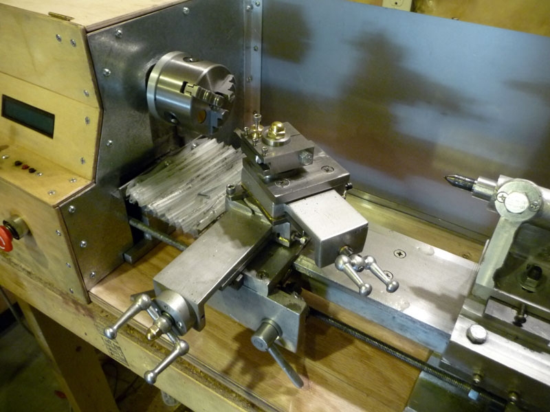
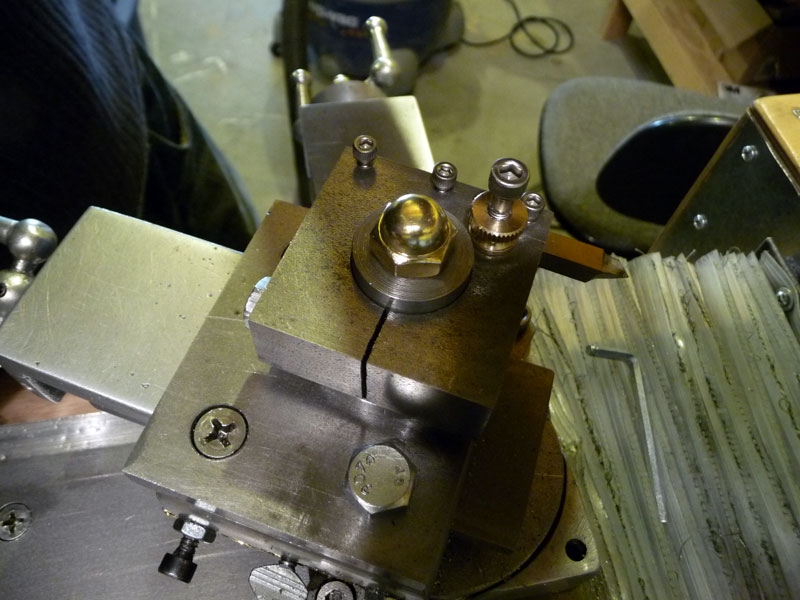
Tool Post Assembly Photos:
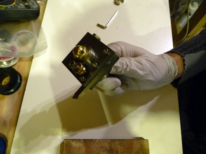
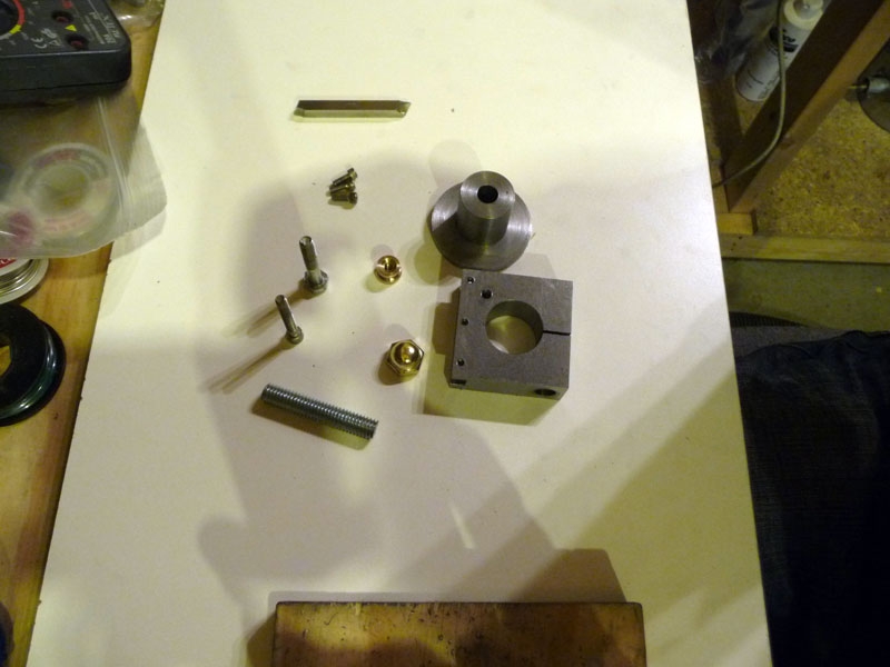
You are now at the point where you can assemble the tool post and test it out. I’m extremely please with how it turned out, and it proved once again that real / accurate work can be done on a home built Gingery Lathe.
Cheers,
Morgan
Hi Morgan,
Very nicely done, I am planning to build this also.
Best regards from the Netherlands,
Jan,
Where can I get the plans for a Norman Patent Style Tool Post? I have looked all over the web. I have an old Atlas lathe that came with a rocker style tool holder.
Hey Ray,
I basically went off of George Carlson’s plans here:
http://www.homemetalshopclub.org/projects/toolpost/toolpost.html
and modified as needed for my machine of course.
Cheers,
Morgan