Paint Can Furnace
with Accessories, Lost Foam Casting and More!
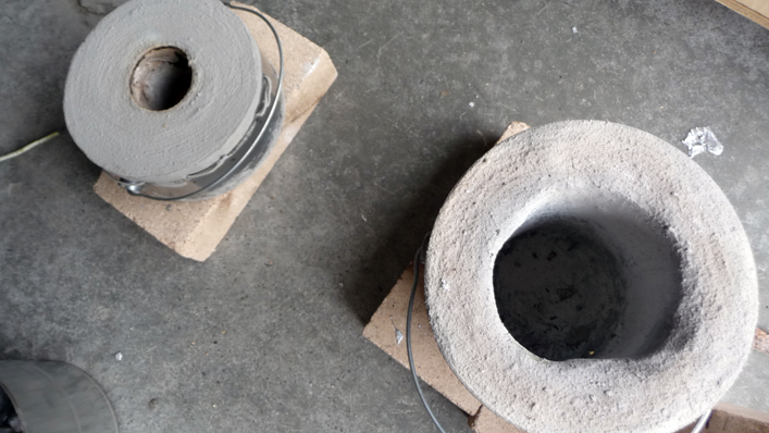
When I started to cast aluminum the end goal was to build a lathe from scratch following the dave gingery machine shop from scrap metal series of books. Now that I have the lathe, I won’t necessarily need to cast large parts all the time, and thus it seemed like a good idea to build a smaller furnace that would be quick to setup, would cool down quickly, and would also be portable. I was initially planning on building a small furnace from a big coffee can, but when in the paint section of a hardware store I noticed new empty paint cans for sale ( for $5 each ), and decided these would be the way to go ( more capacity and I wouldn’t have a bunch of instant coffee to drink ).
Project Index:
Prerequisites: General Tools Required for this Project
- Hand Drill ( drill press is nice to have though )
- Hacksaw
- Basic set of drill bits
- 6-32 tap ( for burner tube locking screws )
- 1/4-20 tap ( for pipe nipple crucible )
- 5/16-18 tap ( for lost foam pressure head tool )
- Tin Snips
- Paper Punch
- Screw Driver ( Philips Head )
- Sharpie
- Straight Edge ( or ruler )
- 2×3 or 2×4 scrap wood for mashing and mixing
- Trowel ( nice for mixing refractory )
- Cheap Paint Brush
- Tarp ( at the very least needed for mixing refractory on )
- Wire Cutter
- Center Punch
- Hammer or Mallet
- Vise
- File
- Foam Cutter ( Utility Knife or Hot Wire Cutter )
- Low Temperature Hot Glue Gun
- JT539t Torch ( or equivalent )
Step 1: Building The Paint Can Furnace
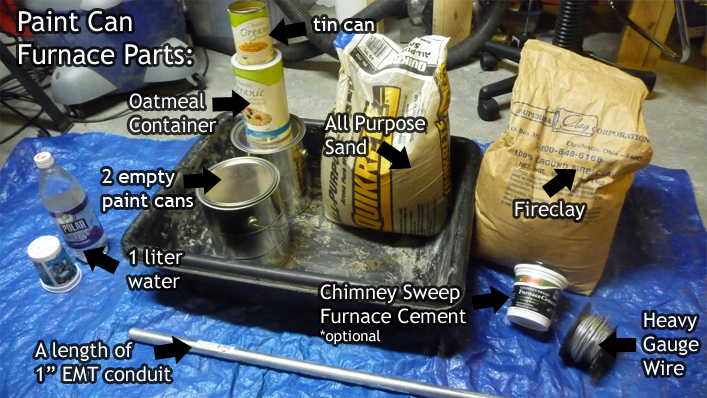
 2 empty paint cans ( $5 each hardware store paint section )
- 50lb bag of all purpose sand
- 50lb bag of fireclay
- 1″ EMT conduit
- heavy gauge wire
- Oatmeal Container with Lid ( furnace body form )
- Tin Can ( furnace lid vent form )
 For this project we will be making the castable refractory mix from scratch, however if you have access to a commercial high temp castable refractory by all means buy that. I’m basically using what Dave Gingery suggests in his Book #1 ( Charcoal Foundry ).
The mix is composed of 2 parts all purpose sand, 1 part fireclay, and 1 liter of water. You will first thoroughly mix together the sand and fireclay, and then, with a spray bottle or plant watering can, apply the 1 liter of water gradually mixing in between. You don’t want any puddles to form as it will separate the sand and fireclay granules which could weaken the mix.
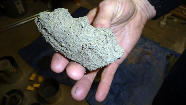 The mix is ready when you can squeeze it in your hand and have it take the shape of it, if it then will break clean in half, and finally if you can squeeze it into a ball, toss it up and catch it without breaking.
Once the mix is done and passes all the tests, cover it with a tarp and let it sit for 12-24 hours. You can work on the furnace lid & body while you wait.
 Take one of the empty paint cans and cut the top 3″ off. My paint cans have ribs and I used those as a guide. I used a hacksaw to cut the can, however it was a bit tedious and probably would have been easier done with tin snips or a dremel tool.
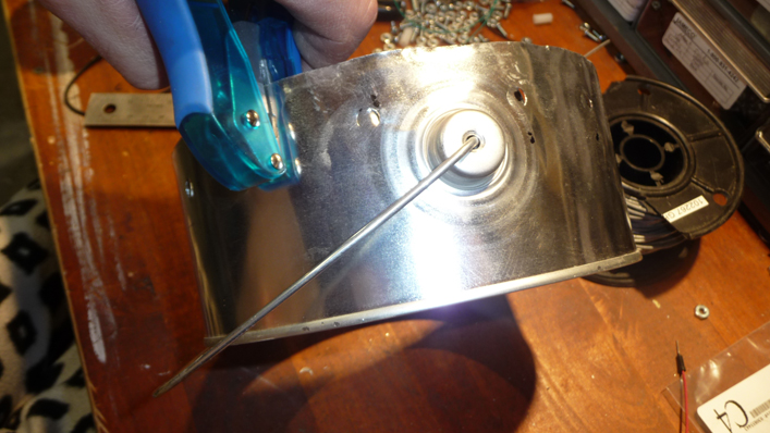 Layout a row of holes around the lid spaced at about 1″ apart. We will be using heavy gauge wire to reinforce the lid as it will be moved around quite a bit. You can use a regular paper hole punch to cut the holes.
To form the furnace lid’s vent hole we will use a regular tin can. Cut the tin can lengthwise, and then compress it with your hand to about 2″ in diameter ( try and keep the can as cylindrical as possible ). Once you have 2″, trim the edges such that there is an overlap of no more than 1″. Mark a row of holes along the edge and cut the holes with a paper hole punch. Cut a piece of heavy gauge wire that will be long enough to weave through the holes such that you can create a seam between the two edges.
Once done, place the vent hole form in the center of the furnace lid, and begin weaving heavy gauge wire through the lid’s holes. This will in effect lock the vent form in the center of the lid. Use the photos to the right, and the video linked above for a better idea of how this should be done.
Remove the lip from the furnace lid, and the other empty paint can with a regular can opener.
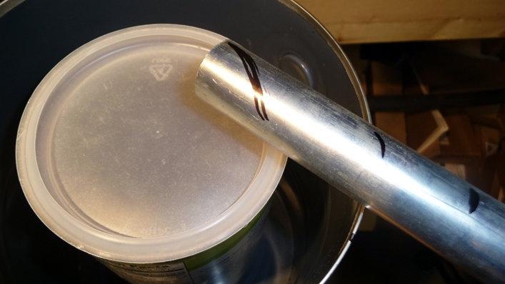 Place the oatmeal container inside the other paint can ( will now be referred to as furnace body ), and lay the 1″ EMT conduit on top of the furnace body such that it is entering the oatmeal container at a tangent. Mark the perimeter of the oatmeal container onto the conduit with a sharpie. Also mark the furnace body on the conduit, and another point 2-3″ past that.
![]() Cut the 1″ EMT conduit with a hacksaw at the two ends ( oatmeal container side, and 2-3″ out from the furnace body ). This piece will now be referred to as the “burner tube”.
Cut the 1″ EMT conduit with a hacksaw at the two ends ( oatmeal container side, and 2-3″ out from the furnace body ). This piece will now be referred to as the “burner tube”.
![]()
![]() Initially I was planning on using my Ron Reil Style Burner with this furnace, and I needed a bit more room inside the tube to fit the burner nozzle. This is not required if you are going to be using something like a JT539t torch by bernzomatic ( recommended ). So, I ended up splitting the burner tube lengthwise, and using my burner nozzle to enlarge the burner tube to accommodate that.
Initially I was planning on using my Ron Reil Style Burner with this furnace, and I needed a bit more room inside the tube to fit the burner nozzle. This is not required if you are going to be using something like a JT539t torch by bernzomatic ( recommended ). So, I ended up splitting the burner tube lengthwise, and using my burner nozzle to enlarge the burner tube to accommodate that.
![]()
![]()
![]() With the burner tube cut and sized, layout the burner tube end profile at the bottom of the oatmeal container. If your oatmeal container has a recess on the bottom, be sure to place the hole above that such that it fully enters the inside of the container. Cut the hole out with a utility ( or x-acto ) knife.
With the burner tube cut and sized, layout the burner tube end profile at the bottom of the oatmeal container. If your oatmeal container has a recess on the bottom, be sure to place the hole above that such that it fully enters the inside of the container. Cut the hole out with a utility ( or x-acto ) knife.
Locate a position for the burner tube to enter the furnace body – about 2″ from the bottom. Use the burner tube once again to layout the burner tube hole, and then drill a hole at the edge of the oval such that you can cut out the hole with tin snips, or a nibbler. Once the hole is cut out place wood blocks at the bottom of the furnace body to raise the oatmeal container enough to check the alignment of the two burner tube holes.
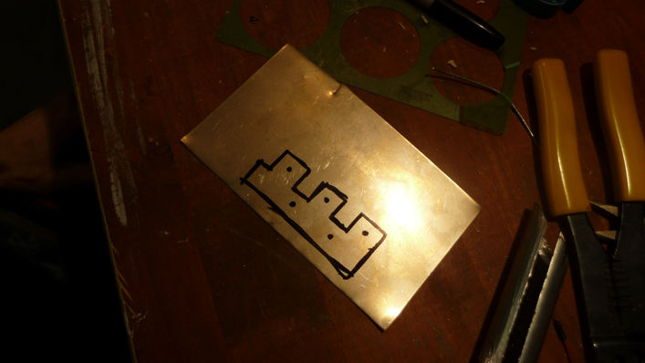 You don’t need one, but I would recommend making a burner tube support bracket that will be mounted to furnace body to help support the burner tube ( versus it just being supported by the furnace wall ). The support bracket can be made from 24 gauge sheet metal. Use the photos to the right to get an idea of how I made mine. It was basically free handed so you can do what works best for your setup.
Drill the mounting holes and then cut out the support bracket. Clamp the bracket at the half way point in a vise and hammer it over to a 90 degree angle. Take the bracket and bend it around the burner tube by hand. Take the burner tube support bracket and place it over the burner tube hole in the furnace body and then mark the locations of the mounting holes. Drill these holes out as best you can. I had to use a piece of wood inside the furnace body while drilling for extra support. With the holes drilled, mount the burner tube support bracket to the furnace body with 6-32 machine screws and nuts. With the burner tube in place, and properly aligned such that it comes into the furnace body at a tangent, adjust the support bracket tabs to a snug fit around the tube.
To finish up the burner tube, mark 3 points equally spaced and 1/4″ – 1/2″ from the outside end of the tube. Center punch the marked points, and drill with a #35 ( or 7/64″ ) bit. Tap the holes to 6-32, and install 3, 6-32 machine screws. If you have the torch that you will be using with the furnace you can test it in the burner tube now.
Re-install the burner tube in the furnace body.
At this point the castable refractory mix should be ready. Start by ramming up a 2″ layer of the mix in the bottom of the furnace body ( a small 2″x3″ or 1″ dowel works well for this ). You want to just about reach the bottom of the burner tube hole. My oatmeal container has a small recess at the bottom, and if yours does to, be aware that you will have to compensate for that in order to ensure that the burner tube is level from furnace body to oatmeal container. Once you have reached the bottom of the burner tube hole, place the oatmeal container at the center of the furnace body, and align the burner tube holes. If you split your burner tube, as I did, insert your burner nozzle in the tube. Place the burner tube in the furnace from furnace body to oatmeal container with very little of it ( if any ) being exposed to the inside of the oatmeal container ( should be sitting on the edge of the cardboard ). You’ll need to make 4 small spacers out of pine that can be used to keep the oatmeal container on center while ramming up the furnace wall. Be sure to place the oatmeal container’s lid on at this point in time, as I forgot to do this till the end, and ended up slightly deforming the container at the top. It was merely cosmetic, but still would have been nice to get a perfect furnace wall. To start, ram up around the burner tube ensuring that you compact the refractory mix all around the burner tube ( we don’t want any voids ). To ram up the furnace wall you will need something along the lines of a 1″ or 1-1/4″ dowel ( wall thickness should be anywhere from 1-1/2″ to 2″). Then proceed to ram up the rest of the furnace wall in a circular fashion with 3 spacers, swapping them out as you go around. Once you reach the top of the furnace body use a small trowel to level off the furnace wall.
The furnace lid is a lot easier to work with, and you’ll simply place it on the ground and ram up the cavity with the castable refractory mix. Once you reach the top use a 2″x4″ or 4″x4″ and a mallet to really compact the mix into the form. I didn’t really bother leveling mine off much, and if you do this on a concrete floor that is in good condition, the bottom of your lid will be pretty flat.
![]()
![]()
![]() Before we can cure the furnace, we’ll need to remove the oatmeal container. This is simply a matter of taking the furnace outside, and lighting the oatmeal container on fire. Once the container is burned out, tip the furnace over and dump out the ash – if you have a shop vac, definitely vacuum up any ash that did not fall out.
Before we can cure the furnace, we’ll need to remove the oatmeal container. This is simply a matter of taking the furnace outside, and lighting the oatmeal container on fire. Once the container is burned out, tip the furnace over and dump out the ash – if you have a shop vac, definitely vacuum up any ash that did not fall out.
![]()
![]() This is now the time to repair any defects that you might have in the furnace wall. You can use the left over castable refractory mix for this purpose.
This is now the time to repair any defects that you might have in the furnace wall. You can use the left over castable refractory mix for this purpose.
![]()
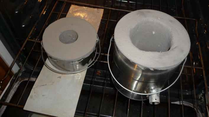
![]() The ‘Paint Can Furnace’ is just the right size to cure in a conventional oven. I’m not sure about ‘commercial refractory mixes’, but it is perfectly safe to cure the homebrew mix in the oven. Simply bake both the lid and furnace body at 275 degrees F. for 2-1/2 hours, and then raise the temperature to 400 degrees F. for 4 more hours.
The ‘Paint Can Furnace’ is just the right size to cure in a conventional oven. I’m not sure about ‘commercial refractory mixes’, but it is perfectly safe to cure the homebrew mix in the oven. Simply bake both the lid and furnace body at 275 degrees F. for 2-1/2 hours, and then raise the temperature to 400 degrees F. for 4 more hours.
This step is not required, but recommended for the longevity of your furnace. When I built my first furnace using Dave Gingery’s homebrew refractory mix recipe, a fellow named ‘wonk’ on the Gingery Machines Yahoo Group recommended that I paint on a thin layer of furnace cement to make the homebrew refractory last longer. Needless to say, it worked amazingly well, and my original furnace is still melting metal and in great shape. The only maintenance I have had to do on that furnace, was an additional application of the furnace cement from time to time.
I’d imagine you should be able to find some variety of ‘Furnace Cement’ locally. The ‘Chimney Sweep’ variety by ‘Rutland’ can withstand up to 2700 degrees F. I’ve seen some other brands just labled ‘Furnace Cement’ but rated to 3000 degrees F. Definitely look around locally, and you really should only need 1/2 pint for this project.
![]()
![]()
![]() Using one of those throwaway rubbermaid sandwich containers, mash up about half the furnace cement with a small amount of water. Gradually add the water until you get a nice thick consistency that can be painted on with a paint brush. Any old piece of wood will do to mash up the furnace cement with the water. Once you have the right consistency, using a paint brush simply paint on a thin layer of the cement onto the furnace base, wall and lid. For the lid you would do the top first, wait about an hour, and then paint the bottom.
Using one of those throwaway rubbermaid sandwich containers, mash up about half the furnace cement with a small amount of water. Gradually add the water until you get a nice thick consistency that can be painted on with a paint brush. Any old piece of wood will do to mash up the furnace cement with the water. Once you have the right consistency, using a paint brush simply paint on a thin layer of the cement onto the furnace base, wall and lid. For the lid you would do the top first, wait about an hour, and then paint the bottom.
 You can cure the furnace cement in your oven as you did the castable refractory. Definitely follow the directions for the furnace cement you purchased, however for the ‘Chimney Sweep’ variety it recommends gradually heating to 500 degrees F. So, in my case at least, I baked at 300 degrees F. for 30 minutes, then 400 degrees F. for 30 minutes, an finally 500 degrees F. for 30 minutes.
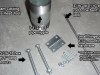
Step 2: Making a Crucible
 2″ BLACK PIPE nipple 6″ long
- 2″ BLACK PIPE nipple cap
- 1 x STAINLESS STEEL 1/4-20 eye bolt and nut
- 2 x 3/16″ steel rod 3′ long
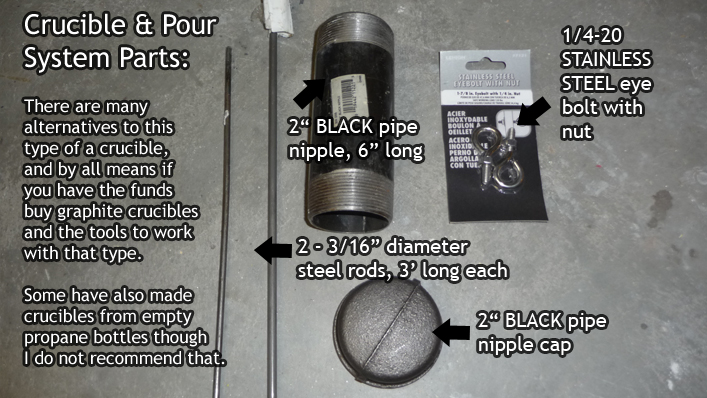
Now that we have a furnace, we need something to melt the metal in. For my larger furnace I used a 2qt cast iron pot, however this is far too big for this sized furnace. 2″ Black Pipe Nipples should be available at your local hardware store, and thus it seemed like a great fit for this particular project. There are other options to choose from, such as purchasing a commercial graphite crucible and special tools to lift and pour it. Or others have used those narrow propane bottles, but I wouldn’t recommend it from a safety standpoint ( though I have never tried to do it myself ).
One other point on safety – be sure to use the ‘BLACK’ pipe nipple and nipple cap varieties. Galvanized pipe contains zinc, and when heated to aluminum melting temperatures will release toxic fumes. Also, be sure to use ‘STAINLESS STEEL’ hardware such as for the eye bolt and nut, as zinc plated hardware will also release toxic fumes at these temperatures ( though not as much as a galvanized pipe ).
![]()
![]() To start, mill or file the bottom of the pipe nipple cap flat enough that it will sit flat and not wobble. Next screw the pipe nipple cap onto the pipe nipple and place it inside your furnace. Mark a point on the nipple just below the top edge of the furnace body. This should be pretty much where the nipple threads end, however it may vary from furnace to furnace. Remove the nipple from the furnace, and cut to size with a hacksaw.
To start, mill or file the bottom of the pipe nipple cap flat enough that it will sit flat and not wobble. Next screw the pipe nipple cap onto the pipe nipple and place it inside your furnace. Mark a point on the nipple just below the top edge of the furnace body. This should be pretty much where the nipple threads end, however it may vary from furnace to furnace. Remove the nipple from the furnace, and cut to size with a hacksaw.
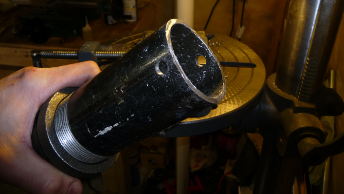 Mark a point on the non-threaded end of the pipe about 1/2″ in from the end. Center punch this mark, and then drill with a 3/8″ drill bit through both ends of the pipe. Ensure that the hole drilled goes through the center line of the pipe.
Mark another point at the threaded end of the pipe, above the nipple cap by about 1/4″-1/2″. This point should line up in the middle of the two 3/8″ holes at the top of the pipe. You will then file the threads flat at the marked point to make it easier to drill. Center punch the mark, and drill it with a #7 ( or 13/64″ ) drill bit. Once drilled, tap the hole with a 1/4-20 tap. Remove the nipple cap, and screw in the STAINLESS STEEL eye bolt. Thread the 1/4-20 nut onto the eye bolt and mark the point on the eye bolt thread that still extends into the pipe. Remove the eye bolt and cut the threads to the marked point ( use a file to clean up the cut mark, filing to a taper will also help ). Screw the eye bolt back into the pipe, thread the nut on the eye bolt from the inside of the pipe, and tighten to lock it into place. Screw the nipple cap back onto the pipe and tighten as hard as you can ( possibly using a monkey wrench ).
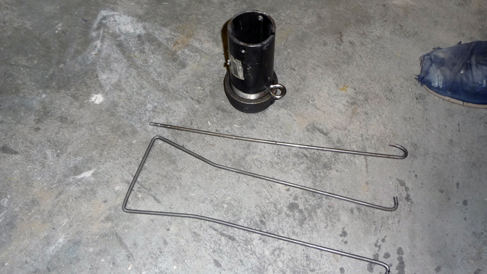
The pipe nipple crucible is now complete.
The lift & pour tools for the pipe nipple crucible are derived from a bigger version that I designed for my larger cast iron crucibles that I use in my other furnace. I prefer this system as the lifting tool needs to be compressed in order to engage the crucible, and thus there is a spring tension keeping the lifting tool engaged with the crucible. It is also a very quick and cheap set of tools to make.
![]()
![]()
![]()
![]() First take a piece of 3/16″ steel rod that is 3′ long. Mark two points 16″ from each end. Clamp the rod in a vise at each mark and bend the rod such that you end up with a U shape.
First take a piece of 3/16″ steel rod that is 3′ long. Mark two points 16″ from each end. Clamp the rod in a vise at each mark and bend the rod such that you end up with a U shape.
 Next mark two points on the U shape about 1/2″ in on each end. You will then bend these in such a way that the two ends of the U shape will be pointing outward. These two ends engage the 3/8″ holes of the crucible from the inside of the crucible.
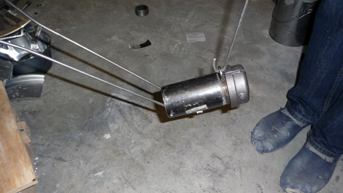
With the lifting tool bent, you then should test it with the crucible. You may need to make some adjustments to the bend, such that the crucible will pivot on the lifting tool when engaged yet still require enough compression to stay engaged with the crucible at all times.
For the pour tool take another piece of 3/16″ steel rod and simply bend a hook at the end.
Some photos of the finished crucible and pour system:
Step 3: Burner Options
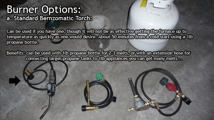 One of my main goals with this furnace was to have a setup that would be portable, and could possibly run off of a 1lb propane bottle if need be for a few melts. I have a BZ8250HT bernzomatic torch which I thought I’d try in the furnace, and it reached 1300 degrees F. in about 50 minutes when run off of a 1lb propane bottle from a cold start. The bottle definitely had some fuel left, so I’d say you could probably get about 2-3 melts in a session from a 1lb propane bottle and the BZ8250HT. To me 50 minutes was not acceptable, as I really wanted something that I could setup quickly – I was hoping for the 15-30 minute range.
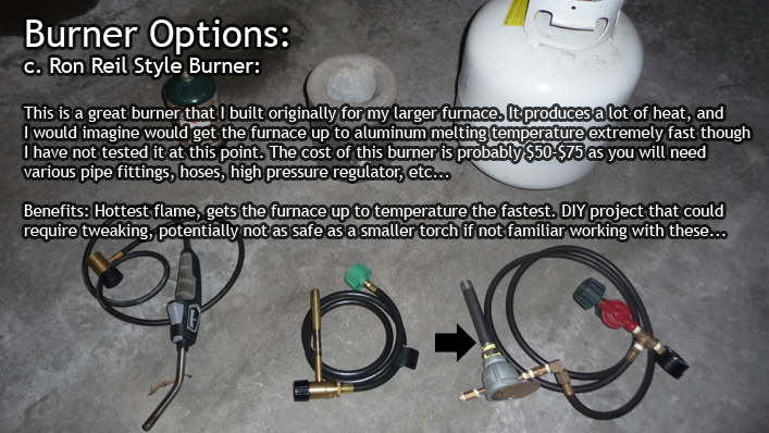 I have a Ron Reil Style Burner that I use for my larger furnace, and adapted it to this one by swapping out it’s burner nozzle with a 1/2″ diameter black pipe nipple. It definitely worked, though seemed a bit overkill for a furnace this size. I didn’t actually try melting any metal with it, but if I ever need higher temps I’ll probably switch over to this burner. For the beginner, I wouldn’t recommend a Ron Reil Burner for this furnace as it really isn’t needed, and possibly not as safe to operate as a commercial torch. I also priced out the parts required and the cost would come in at about $50-$70 which was more than the next option.
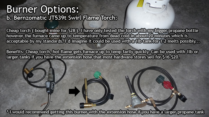 I began looking into other torches on the market, and the bernzomatic JT539t swirl flame torch seemed of interest. It’s marketed as a brazing torch with a hotter / more efficient flame. For $28 at my local hardware store it seemed like a steal so I purchased one, and also bought an extension hose kit to hook it up to my larger propane tank. This torch definitely produced a much more substantial flame than the BZ8250HT, and when I tried it out I was sold that it was the way to go for the ‘Paint Can Furnace’. From a cold start the furnace was up to 1320 degrees F. in about 20 minutes while running off of my larger propane tank. The BZ8250HT probably would have been faster than 50 minutes if I connected it to my larger tank, but I still feel that the JT539t produces more heat and will do the job faster. I believe this torch could also be used with the smaller 1lb propane bottles, though you may only get 1-2 melts out of it.
Step 4: Casting Options
Now that we have the furnace, crucible, lift & pour tools, and a burner it’s time to think about what we want to cast and how we will go about doing it.
 With lost foam casting you can cast much more complicated pieces than the traditional casting method, as you don’t have to worry about removing the pattern from the mold. At the very least you should be able to start casting with just play sand, a vessel to hold the sand, and a foam pattern. The results may not be perfect, but I’m recommending starting off with lost foam casting simply because it will be the quickest way to cast a potentially interesting / complex part without needing to make all the molding tools.
Lost Foam Casting Tools Required:
- High Density Pink, or Blue, Foam Insulation Board
- Hot Wire Cutter ( not required, could be cut with a utility knife probably )
- Card Stock ( if using Hot Wire Cutter, Card Stock makes a perfect template )
- Low Temperature Glue Gun ( for joining foam pieces )
- Pressure Head Tool ( not required, but highly recommended )
Lost Foam Casting in Play sand
If you don’t have any casting tools, you should start off by using the bottom half of the paint can used for the furnace lid as the vessel to hold the sand / foam pattern.
Lost Foam Casting in Greensand or Petrobond
 If you have some greensand, or Petrobond, and are not getting the surface finish you want with loose play sand, you can try lightly ramming up your foam patterns in greensand or Petrobond. I ended up using this method for the test / results below and am extremely pleased with the surface finish.
 This option requires many more tools, and time, than Lost Foam casting. The main benefit to use this method is that the pattern can be used over and over again. There are also some potential health risks involved with Lost Foam – burning out the foam, or cutting the foam with a hot wire cutter, etc…
Greensand Casting Tools required:
 greensand or Petrobond
- 2 part flask
- ramming tool ( can be a 2×4 to start )
- parting dust in a sock ( can use talcum powder )
- gate cutting tool ( spoon or palette knife )
- sprue & riser cutting tools ( 3/4″ and 1/2″ copper pipe )
- riddle, or fine mesh sifter
- molding bench ( not needed but helpful )
- wood working tools to make patterns
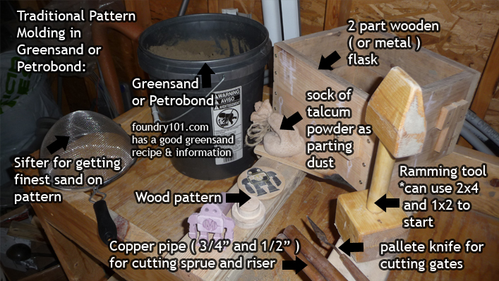
What is greensand? It is simply a mix of fine sand, southern bentonite and water. There is so much information at foundry101.com that I won’t get into it much further and will simply recommend checking out their website, or purchasing Dave Gingery’s Book #1 ( Charcoal Furnace ) for his recommendations. Petrobond is a commercial product that is bonded with oil instead of water ( though there are some homebrew recipes floating around the net ).
Step 5: Making a Pressure Head Tool for Lost Foam Casting
 1-1/2″ pipe nipple 5″ long
- small hinge
- 4 x 8-32 machine screws and nuts
- 2 x 5/16-18 bolts 5″ long with nuts
- 3/16″ steel rod

The pressure head tool will keep molten metal flowing into the foam pattern as the foam is burned out. If you have a welder I would recommend welding the tool versus bolting it together. I don’t have a welder and have found the bolt together version to be satisfactory. For more information on this type of tool, checkout Dave Kush’s Lost Foam Metal Casting Primer.
![]()
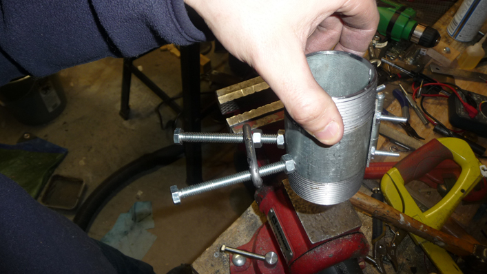
![]() To start, draw a line down the length of pipe where you will be cutting it in half. You can then place the hinge over the line and mark out the hinge bolt holes. With a hacksaw, cut the pipe in half using the line as a guide.
To start, draw a line down the length of pipe where you will be cutting it in half. You can then place the hinge over the line and mark out the hinge bolt holes. With a hacksaw, cut the pipe in half using the line as a guide.
![]()
![]()
![]() With the pipe cut in half, clamp the two sides together in a vise and drill one side of the hinge’s hole marks with a #16 ( 11/64″ ) or larger drill bit. Mount the hinge to these holes with 2, 8-32 machine screws and nuts. Use the hinge to ensure that the marks on the other side still line up, if not adjust accordingly. Be sure to center punch the marks before drilling to prevent the drill bit from wandering on the pipe. Drill the holes on the other side of the hinge and finish mounting the hinge with 2 more 8-32 machine screws and nuts.
With the pipe cut in half, clamp the two sides together in a vise and drill one side of the hinge’s hole marks with a #16 ( 11/64″ ) or larger drill bit. Mount the hinge to these holes with 2, 8-32 machine screws and nuts. Use the hinge to ensure that the marks on the other side still line up, if not adjust accordingly. Be sure to center punch the marks before drilling to prevent the drill bit from wandering on the pipe. Drill the holes on the other side of the hinge and finish mounting the hinge with 2 more 8-32 machine screws and nuts.
![]()
![]()
![]() Locate and mark two points on the pipe at the opening of the hinged pipe. This will be where the handle bolts go. The location vertically doesn’t matter, though the bolts should be spaced close together at the cut edge of each half. Center punch and then drill the two marks with an F ( or 17/64″ ) drill bit. Once drilled, tap the holes with a 5/16-18 tap. Thread a nut on each of the 5/16-18 bolts, keeping the nut toward the end of the bolts. Screw the bolts into the holes, and adjust the locking nuts such that the bolts do not extend into the middle of the pipe.
Locate and mark two points on the pipe at the opening of the hinged pipe. This will be where the handle bolts go. The location vertically doesn’t matter, though the bolts should be spaced close together at the cut edge of each half. Center punch and then drill the two marks with an F ( or 17/64″ ) drill bit. Once drilled, tap the holes with a 5/16-18 tap. Thread a nut on each of the 5/16-18 bolts, keeping the nut toward the end of the bolts. Screw the bolts into the holes, and adjust the locking nuts such that the bolts do not extend into the middle of the pipe.
 The final step to building the pressure head tool is to make a lock such that the tool will not open while it is being filled with molten metal. You can fashion a quick lock out of a piece of 3/16″ steel rod by bending it into a C shape that will fit over the two handle bolts and slide outward locking the two bolts together. You can use one of the 5/16-18 handle bolt toward the bolt’s head to fashion the ends of the lock ( so you don’t damage the threads ).
The finished pressure head tool:
Step 6: Lost Foam Pattern Making
- Pink, or Blue, High Density Foam Board Insulation
- Hot Wire Cutter, or Utility Knife
- Low Temperature Hot Glue Gun
- Card Stock ( good template for hot wire cutter )
- Scissors ( if using card stock )
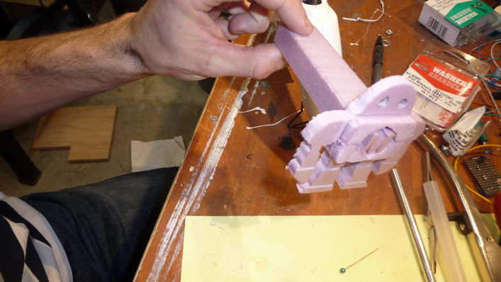
It’s a fairly simple process to make a basic pattern in foam. You simply cut out the pattern, and attach a sprue ( where the molten metal will flow into the pattern ). You don’t need a hot wire cutter to get started, but it will do a fantastic job at producing very smooth cuts in the foam. I built a quick hot wire cutter by following the Make: 5 Minute Foam Factory Project. If you don’t have, or want to build a hot wire cutter, a utility knife should allow you to cut out some basic shapes to get started.
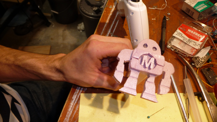
It has been my intent to add this project to makeprojects.com, though at this point they are not taking new members. I mainly state this fact as the patterns I created were related to Make Magazine, and typically I wouldn’t spend my time making patterns like this. Anyways, the MakerFaire Robot seemed like a neat pattern to cast using lost foam, so that is what I made for this tutorial.
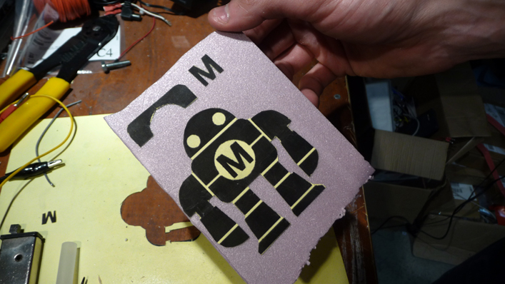
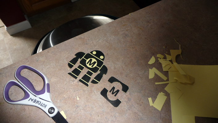 To start I printed the various parts of the pattern onto card stock. The parts were cut out of the card stock and then glued to the piece of foam. The hot wire will not cut through the card stock, and thus it makes a perfect template to cut out complex patterns. The foam parts were then cut out using a hot wire cutter, and glued together with a low temperature hot glue gun. You need to use a low temperature hot glue gun, as the higher temp ones will melt the foam.
 Once you have your pattern in foam you will need to attach a sprue to it such that the molten metal can flow into the pattern. Simply cut out a 1″x1/2″x5″ piece of foam and glue it to a major area of the pattern. If you take a look at Dave Kush’s Lost Foam Primer, he uses a split sprue which feeds multiple parts of the pattern at once, and is probably a good way to go for more complex patterns.
At this point you can use the foam pattern as is, or you could coat it with drywall mud to get an even better surface finish. You have to let the mud dry for a few days which for me defeats the rapid prototyping angle of lost foam casting – I just want to be able to make a pattern and cast it in the same night, so I skipped this step in the tutorial. You may find that the surface finish of the high density foam without drywall mud is perfectly acceptable for what you are doing.
Step 7: Bedding a Foam Pattern in Sand
If you don’t have any tools, greensand, or Petronbond this would be the best way to go to get started. Simply use the bottom half of the paint can, used for the furnace lid, as the vessel to hold the play sand and pattern.
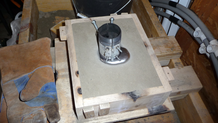
Place a 2″ layer of play sand at the bottom of the vessel, and then place the foam pattern on that with sprue pointing up. Fill the reset of the vessel with play sand until you have a small bit of the sprue exposed. Shake, or tap, the vessel a few times to get the play sand to fill in any voids around the pattern. If the sprue is too tall, you can trim it down with a hacksaw blade. Place the pressure head tool over the sprue, and you are ready to pour.
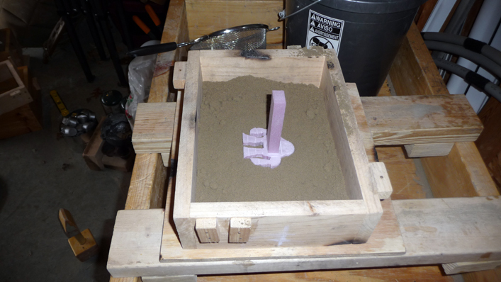
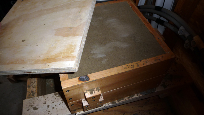
I’ve read that you can get an even better surface finish from the lost foam pattern if you lightly ram it up in greensand, or Petrobond. Since I have greensand I decided to use this method to bed the pattern I made in step 7. If you want to try this method after giving the loose play sand a try, you can buy small batches of Petrobond which should produce great results.
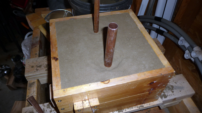
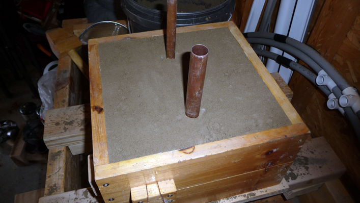
Take a vessel of some sort, I’m using the drag half of a molding flask since I have them lying around – you could use the bottom half of the paint can used for the furnace lid as well. Add a 1-2″ layer of sand to the bottom of the vessel, and then using a sifter, sift some of the sand over where you will be placing the pattern. Lightly press the pattern into the sand with the sprue facing up. Sift some additional sand over the exposed foam pattern, and then fill in the vessel by another 1″-2″. Once done lightly ram up the sand with a 2×4 ( or ramming tool if you have one ). Continue to do this until the vessel, or half flask is filled to the top. Trim the sprue such that no more than 1/4″ is above the sand, and then cut a funnel shape out of the sand around the sprue. Place the pressure head tool over the sprue, and you are ready to pour.
Step 8: Traditional Wood Pattern Molding
I’m including this step simply as a means to give you an idea of the process of creating a mold from a wood pattern for casting. I also wanted to show the difference between this method and lost foam, and the results from the two different casting methods.
To start off with you would make a pattern out of wood. It’s critical to add draft to the pattern such that you can remove it from the sand before closing the mold. You also have to add fillets to 90 degree angles to also aid in pattern removal.
Once you have the wood pattern to cast, you will most likely need a 2 part flask to create the sand mold and remove the pattern. The top is called the cope, and bottom the drag. Typically the two halves are rammed up in such a way that you open the flask, remove the pattern and close the flask before the pour.
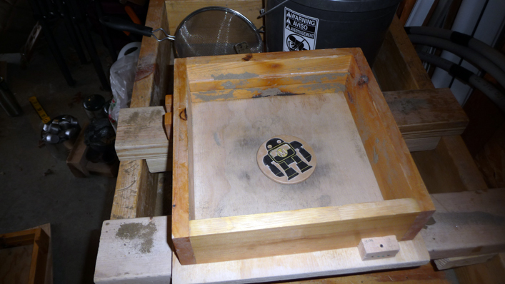
For the simple pattern I’ll be casting in this project, lay the pattern down face up on a molding board with the drag placed over it top down. Dust the pattern with parting dust ( talcum powder in my case ), and then sift some greensand, or Petrobond, over the pattern. Fill the drag with sand to about 2″ and then ram the sand with a consistent amount of force. You can either use a 2×4, or specially designed ramming tool, to ram up the sand. Continue adding layers until you reach the top ( or should I say bottom ) of the drag, and then score off the sand with a piece of wood. Sprinkle on a little extra sand, and then rub on a molding board.
 Flip the drag over, and then remove the top molding board which will reveal the bottom of the pattern. You will then place the cope half of the flask on the drag, and then dust the pattern / sand again with parting dust. Take note of where you want to cut the sprue and riser with a piece of chalk, on the outside of the flask. Sift some sand over the pattern, and then fill again by ramming up multiple layers of sand until you reach the top of the cope.
 Score off the sand, and then using a 3/4″ copper pipe for the sprue, push it down where you marked for the sprue until you reach the parting line ( line between the cope and the drag ). Do the same for the riser except using a smaller 1/2″ copper pipe. Using a palette knife cut funnels around the two copper pipes and then clear out the sand by hand or with a brush. Remove the copper pipes, and then with your thumb lightly press and form the funnel such that there is no loose sand ( don’t want it to wash into the mold when pouring the metal ).
Rap the flask ( tapping it with your 2×4 or whatever ) to make it a bit easier to separate the two halves. Open the flask, and then cut gates from the sprue and riser to the pattern that still is in the sand. Once the gates are cut, lightly rap the pattern and remove it from the sand. You are now ready to carefully close the flask. Close the flask, and if all goes well you are ready for the pour.
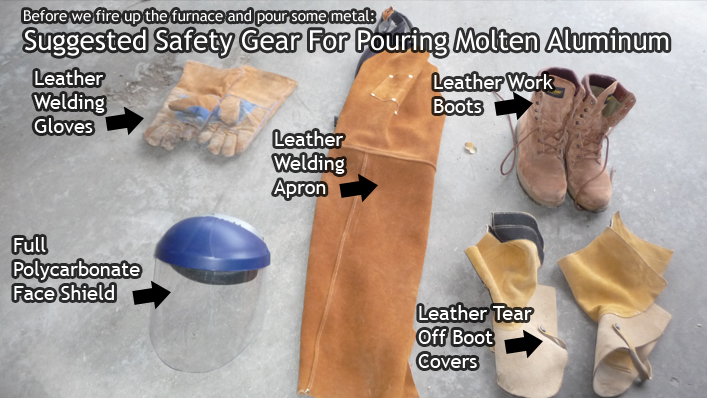
Step 9: Safety Gear
You can never be too safe when working with a hot furnace, molten metal, etc… I would definitely recommend the following safety gear, and it is what I have worn since I began casting aluminum. It only takes one mess up to ruin your life, so use your head and be safe.
 Full Polycarbonate Face Shield
- Leather Boots
- Leather Boot Covers
- Leather Welding Apron
- Leather Welding Gloves
Step 10: Sourcing Aluminum To Melt
At first it can seem a bit daunting of a task trying to find some scrap aluminum to melt in your furnace. I started out calling all the local ‘small engine’ repair shops in my area, and found quite a few that had broken engine parts waiting to be recycled that they were willing to give to me for free. That got me mostly through the metal I needed for my lathe, and then a neighbor was getting rid of a broken lawn mower, which I gladly took apart for the aluminum. Aluminum rims are another good source of aluminum to cast in your furnace, though it is an extremely tedious process cutting the rims up ( especially if you want to fit the pieces in the 2″ pipe nipple crucible ). I found 2 such rims at a local recycling store for $10, what a find. You may have good luck using an angle grinder to cut up larger pieces of aluminum, but I haven’t tried it myself ( though I want to at some point when I buy an angle grinder ). Finally, if you don’t want to search for scrap, you can always buy clean ingots from Budget Casting Supply ( 15lbs for $58 including shipping ).
Materials that some may suggest for aluminum scrap, that probably aren’t that good to use ( but could be used to try it out ). Aluminum cans, aluminum extrusions, etc… Any cast aluminum part ( engine blocks, pistons, rims, etc.. ) is perfect scrap for melting in your furnace, as you can be sure the aluminum alloy was designed specifically for casting.
That being said, once you have some scrap aluminum make sure it doesn’t have magnesium by cutting off a small piece and burning it with a torch. If it is magnesium it will catch on fire, otherwise it should just melt into a blob. I would recommend buying a firebrick to do this on from your local masonry, or hardware store.
You will also want to have an ingot mold to pour any excess metal in your crucible into when you are done with your casting session. I use a cast iron mini muffin pan which works perfectly, and creates ingots that are perfectly sized to fit inside the 2″ pipe nipple crucible. I basically use my larger furnace with a 2qt cast iron crucible to melt down larger pieces of aluminum. I then pour them in the mini muffin pan ingot mold to make ingots for my smaller ‘Paint Can Furnace’. You probably won’t be able to do this at this point, unless you have a larger furnace, but it is the best way to go if you plan on melting a lot of metal.
Step 11: Melting Aluminum in the Paint Can Furnace
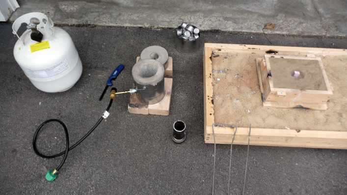 If you have gotten to this point you should be ready to go, and have something to cast. To start prepare your pattern / mold, and then get everything setup for the melt and pour. I didn’t go over building one, but I would recommend making a shallow box at least 2′x2′ with play sand 1″-2″ deep. You should always pour over sand and would place your flask, or lost foam pattern’s vessel, in the center of the sand bed. When setting things up be sure to place the furnace right next to where you will be pouring. This will eliminate any need to walk around with a crucible full of molten metal. With my setup I really only need to take one or two steps to the side to do the pour.
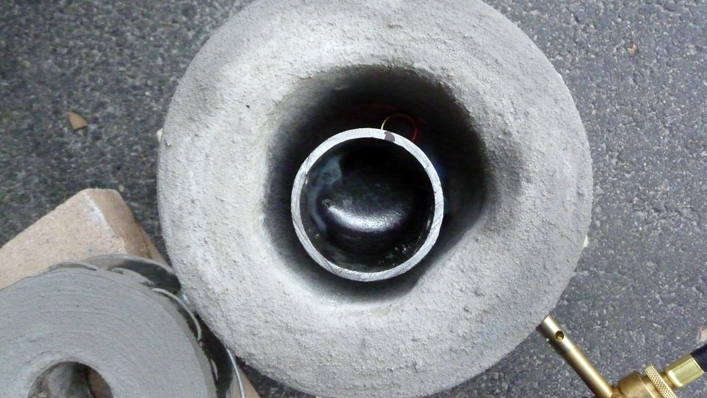 With everything setup, start the furnace and then fill the crucible with aluminum. Using the lifting system, place the crucible in the furnace and then place the lid on the furnace. I have a pyrometer that I use to check the temperature of the furnace before I pour. For lost foam casting I like to get the temperature to 1300-1400 degrees F. and the pyrometer is a great tool to ensure you are getting to these temperatures. Aluminum will melt at 1220 degrees F. so once the aluminum is liquid in the crucible let it sit for a few minutes before you pour if doing lost foam without a pyrometer.
Once the aluminum is liquid, and has reached pouring temperature, you’ll most likely need to skim off some dross that has settled at the top of the crucible. You can fashion a quick dross skimmer out of a piece of 1″ wide steel flat bar stock 1/8″ thick with a 90 degree angle bent at the end. You simply skim off the top and tap it into the sand bed you are pouring over.
Now you are ready to pour the aluminum into your mold ( or sand vessel holding the foam pattern ). For lost foam, you will be pouring into the pressure head tool. You’ll want to pour as consistently as possible into the pressure head tool, until you notice that no more metal is being accepted ( don’t let the pressure head tool overflow ).
If you are pouring into a traditional greensand mold, with a riser, you would pour into the sprue until you see metal fill up into the funnel of the riser.
If there is any metal left in the crucible after pouring, either place the crucible back in the furnace if you have another mold to pour, or pour the remaining metal into your ingot mold.
For actual details of the pour be sure to checkout the video link at the top of this page.
Step 12: Casting Results
After the pour:
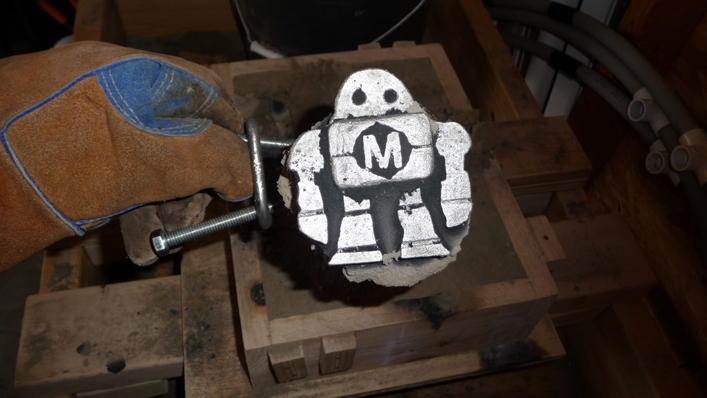
Casting first out of the sand:
Casting brushed off:
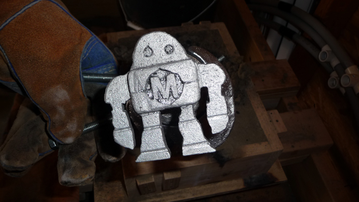
So as you can see, the results of lost foam casting without drywall mud are quite good. There are really no defects in the casting, and what would appear to be a defect is actually a defect in my foam pattern, not the casting itself ( left leg for instance ). The surface finish could be even better I’m sure if I had used drywall mud, but this is definitely satisfactory for the kind of work I’ll be doing.
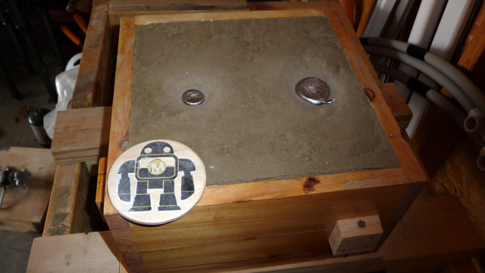
After the pour:
Casting out of sand and cleaned off:
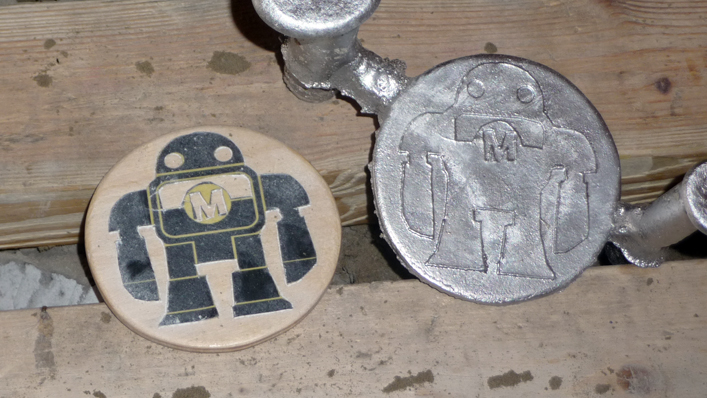
The results turned out quite good, and as you can see, with 100 mesh olivine sand you can pick up the detail of card stock glued to a wood disk. That being said, for complicated patterns that are hard to remove from a sand mold I’ll probably start using lost foam more often.
The furnace held up quite well, and there were no signs of any cracking after it cooled down completely. Over time you’ll notice some hairline cracks form in the furnace cement, but those are easily fixed with another application of furnace cement painted on.
Well that just about covers this project. I hope this information was of some use to you, and will help you reach your goal to casting aluminum.
Cheers,
Morgan
I have a question. You said that you swapped out the 3/4″ burner with a 1/2 black pipe. How did you do this? I could not find a 3/4 to 1/2 coupling. I really appreciated the great way you explained the entire process from beginning to end. Thanks
Hey Calvin, I used a 3/4″ x 1/2″ Black Hex Bushing like this:
http://www.hardwarestore.com/black-hex-bushing-242297.aspx
—
One thing to note, this worked perfectly when using my bigger burner on the smaller furnace, but when using the smaller 1/2″ pipe in my bigger furnace I had stability issues with the flame ( not sure exactly why at this point, but I don’t use a flare at the end of the burner tube and possibly the larger furnace body or the gap between the 1/2″ pipe and the burner hole are culprits ).
—
Cheers,
Morgan