With the tailstock completed, it was time to finish up Gingery’s book #2 by making a permanent spindle for the lathe. I spent quite a bit of time trying to figure out the best spindle to make within my capabilities up to this point ( I also asked the gingery yahoo group for suggestions as well ). I really wanted to be able to buy some chucks for the machine such that I could start doing chuck work sooner than trying to build the Gingery 4-jaw chuck. I had found a 5/8″ to 1″-8 threaded adapter which initially seemed like it would possibly work out, but I really wanted a larger spindle nose than 5/8″. I didn’t feel comfortable cutting threads on the nose with a die, and since the lathe has no threading capability, a threaded nose was out of the question. The spindle that I decided to build has a 3/4″ blunt nose with an MT1 taper socket ( for a dead center such that I could still turn between centers ). Unlike in the Gingery Book, my spindle has a 3/4″ diameter through both headstock bearings, and then reduces to 5/8″ outboard for the drive pulley. All of the Gingery accessories are setscrew mounted, and it has happened quite a few times that, under heavy load, the faceplate has rotated on the shaft and the setscrew severely gouged the temporary spindle. So I decided to mill flats on the spindle wherever a setscrew would be applied. This would provide a good bearing surface for the setscrews, and also prevent the accessory / pulley from rotating on the spindle under heavy load / stall situations.
One other concern was that my faceplate had a 5/8″ bore, and I would need a way to increase that to 3/4″ on the lathe. I ended up making the setscrew chuck from book #6 with a 3/4″ bore, and planned to use that backwards on the new spindle nose to bore the faceplate to 3/4″.
Video:
Making A Permanent Spindle Video »
Spindle Specs:
a. 10″ long
b. 3/4″, 1-1/2″ long spindle nose
c. 5/8″, 2″ long section for outboard drive pulleys
d. 1/4″ flange before nose to act as a bearing surface & register for accessories.
e. Milled flats for better setscrew mounting ( could be filed )
Turning down the Spindle:
The spindle was turned down from a piece of 1″ round CRS ( 1018 ) stock cut to 10″. Center holes were located by marking each end with a sharpy, and then setting my dial caliper to 0.5″ and scribing many lines across the end ( the intersection of the lines reveals the true center point ). The centers were center punched, and then center drilled such that the stock could be mounted between centers on the lathe.
It was a bit tricky turning down the full 10″ length. There was a substantial amount of chatter at the headstock end, while the tailstock end cut perfectly. I reached out to the gingery yahoo group, and received quite a bit of insight / help there, though it ended up that my temporary spindle had 0.005″ runout in it – something I should have checked with my dial indicator right off, but I hadn’t thought of it at the time. To correct the runout I split the headstock bearings such that I could further bear down on the spindle and get a tighter fit. The runout was removed at that point, and the chatter at the headstock end disappeared ( thankfully… ). I still ended up turning the spindle down in two parts, mainly cutting at the tailstock end – since the stock was clamped at one end by a dog, it would have to be flipped end to end to machine the full length anyways.
Photo of the turned down spindle, prior to milling flats and cutting the MT1 socket:
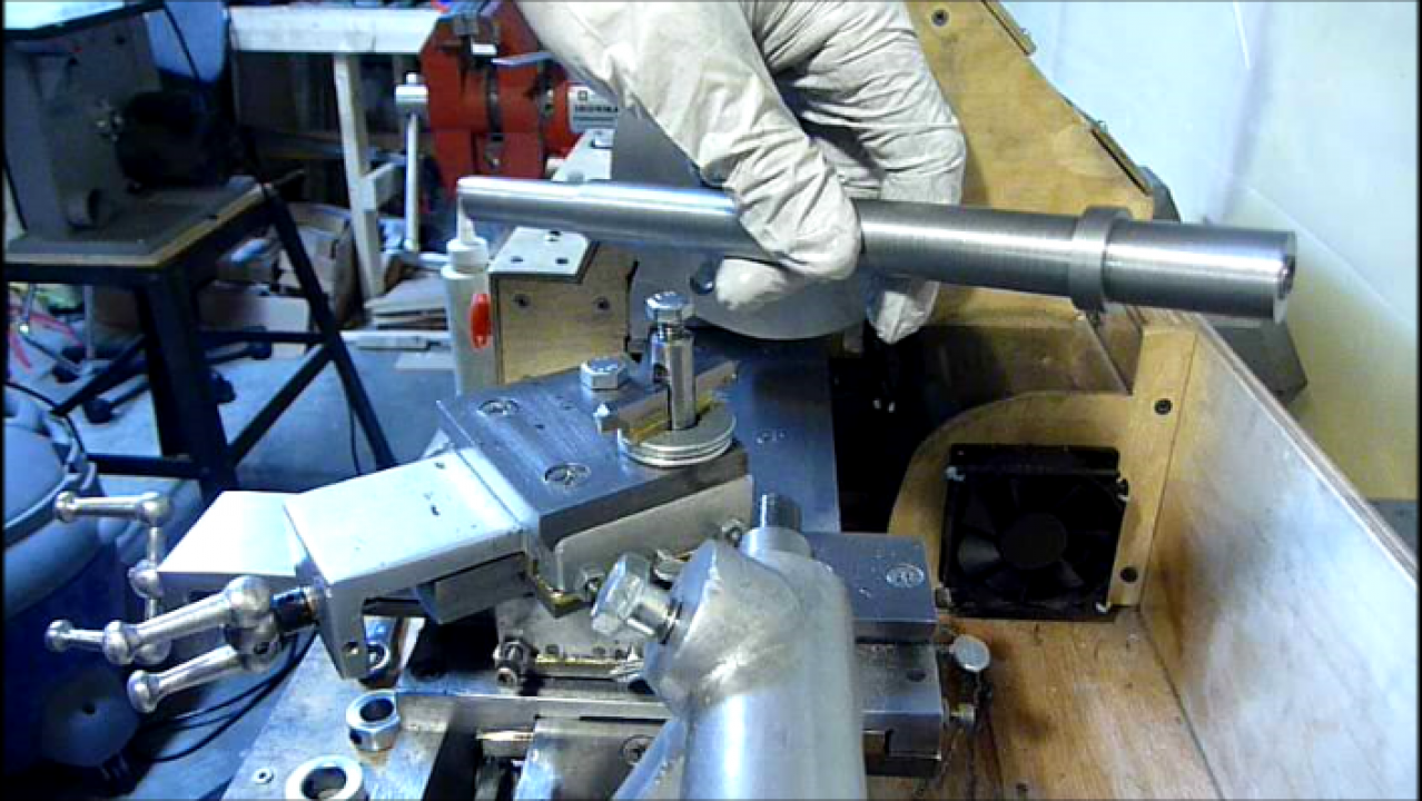
Photo of the spindle with flats being milled:

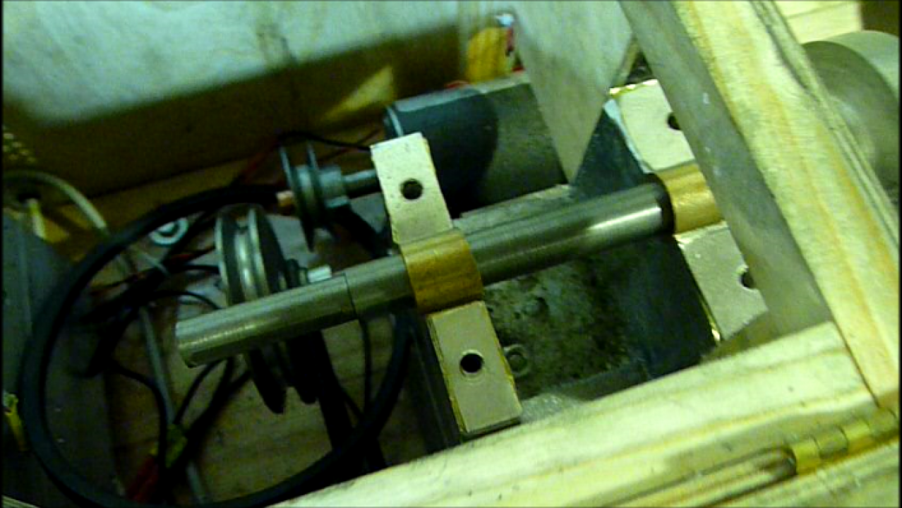
Photo of the spindle installed in the lathe:
Cutting the MT1 Taper Socket:
I was concerned with my ability to cut an MT1 taper socket with the lathe’s compound, as it only had a 1.5″ travel up to this point. I took a closer look at the compound and realized that there was still room to increase the compound’s ways and get more travel out of it. After replacing the compound ways, I was able to get 2-1/4″ travel out of the compound which was enough to cut the MT1 socket in one pass.
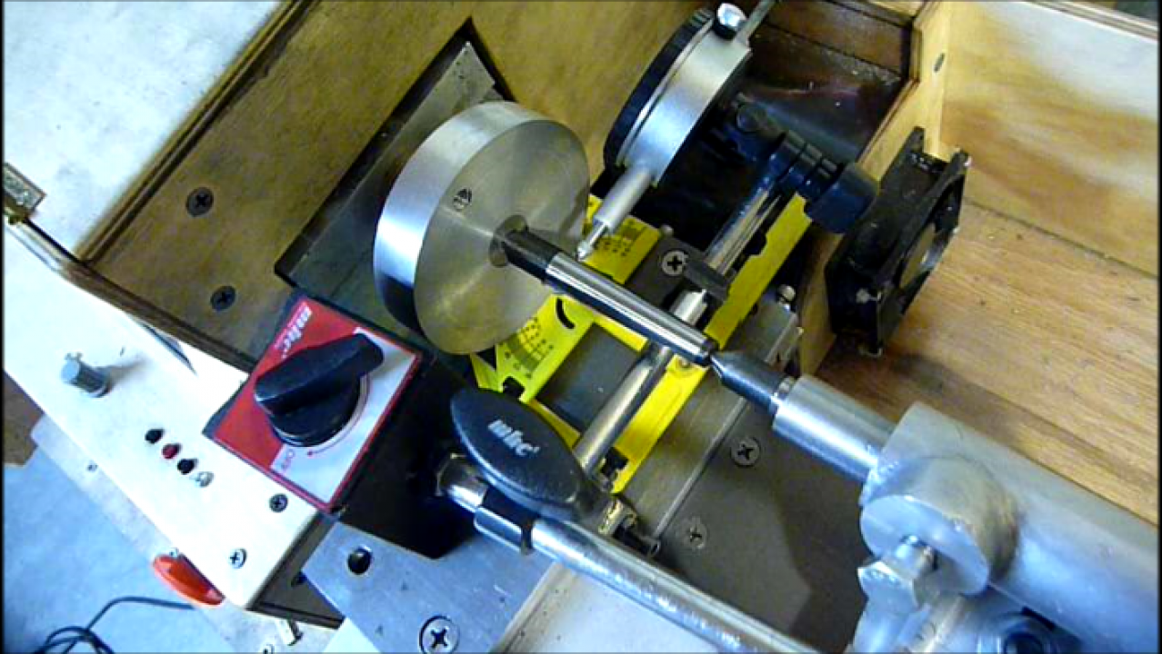
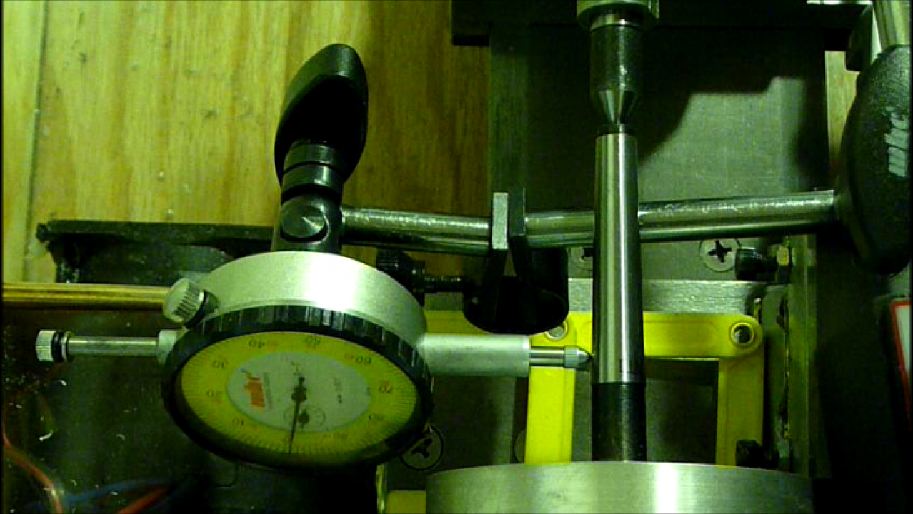
With the compound capable of traveling the require distance, it was time to dial in the compound angle for the MT1 taper. Since the new spindle had a center hole that was on center with the lathe already, I mounted an MT1 dead center between the spindle and the tailstock center ( the dead centers I have, have center holes at the back side ). I then used a dial indicator with magnetic base mounted to the compound to determine when the compound’s angle matched that of the MT1 dead center.
Photos of my setup to dial in the MT1 angle on the compound:
With the compound angle dialed in, the spindle nose was step drilled to 5/16″, 3″ deep with the tailstock’s drill chuck. The 5/16″ hole is big enough to accommodate the 1/4″ boring bar that I have.
Once the 5/16″ hole is drilled to size, the boring operation begins. It’s a bit tight at first, as there isn’t much side clearance for the boring bar + cutter initially. Since a taper is being cut you can hear the end of the boring bar running into the other side if you aren’t too careful. Also, with the required overhang to cut the taper socket, and since I’m using a 1/4″ boring bar, there is a substantial amount of flex in the bar. Don’t despair, keep making multiple passes at the same cutting depth and you’ll be able to get the job done.
Once the taper was cut deep enough such that an MT1 dead center would fit 1/3 of the way in, I mounted a dial indicator to the bed ways, and did a wobble test to see if the fit was accurate or not. My initial reading showed a wobble of 0.007″, and small adjustments were made to the compound angle ( painstakingly on a gingery lathe ) until the wobble was reduced to 0.001″. With the correct angle dialed in, boring continued until the taper was completed.
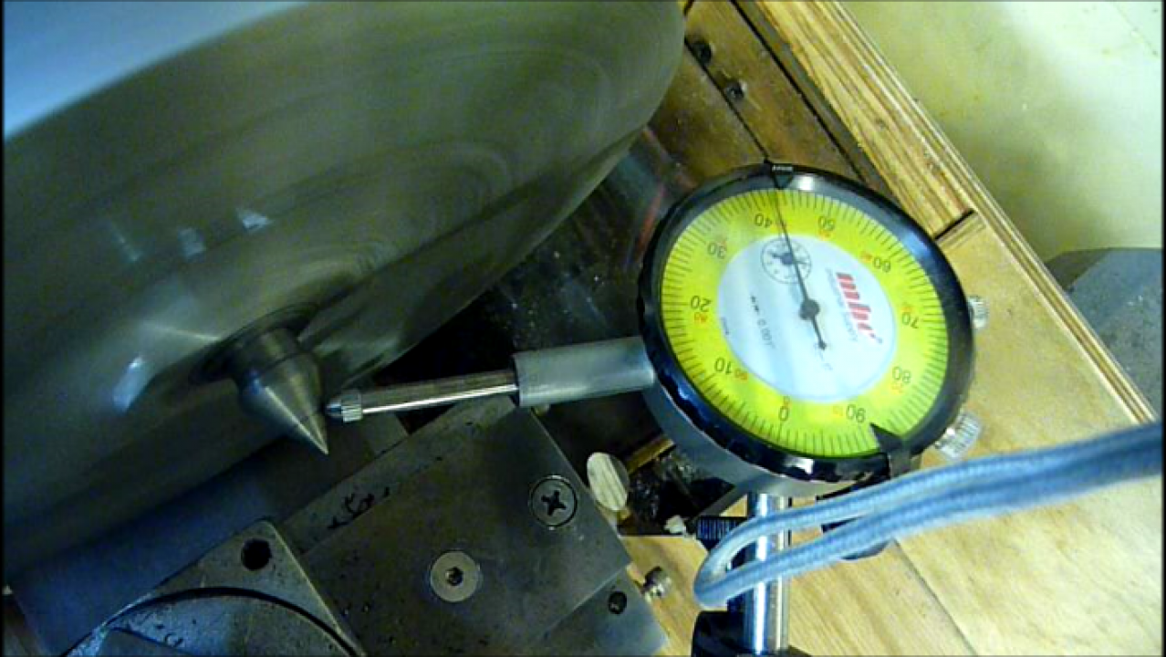
With the taper socket bored, it was time to run a few tests. With the dead center mounted in the socket the wobble test was done again to verify that I still had 0.001″ or less ( check ). I then proceeded to check the alignment of the taper / spindle center with the tailstock center ( check ), and finally I proceeded to test the runout on the spindle center with a dial indicator mounted to the bed ways. Suprisingly, there was a 0.003″ runout on the spindle center… I tested the spindle nose, and the runout there was less than 0.001″ so it wasn’t that. Either the taper wasn’t perfectly centered, or my dead center was slightly bent. At any rate, since the compound was still set to the MT1 angle, I made a witness mark such that I could dial it in at a later date, and proceeded to turn down a new dead center on the lathe. With the new center mounted in the spindle socket, the runout read ~0.001″ which was what I had been looking for initially.
Photo of spindle center & tailstock center alignment:
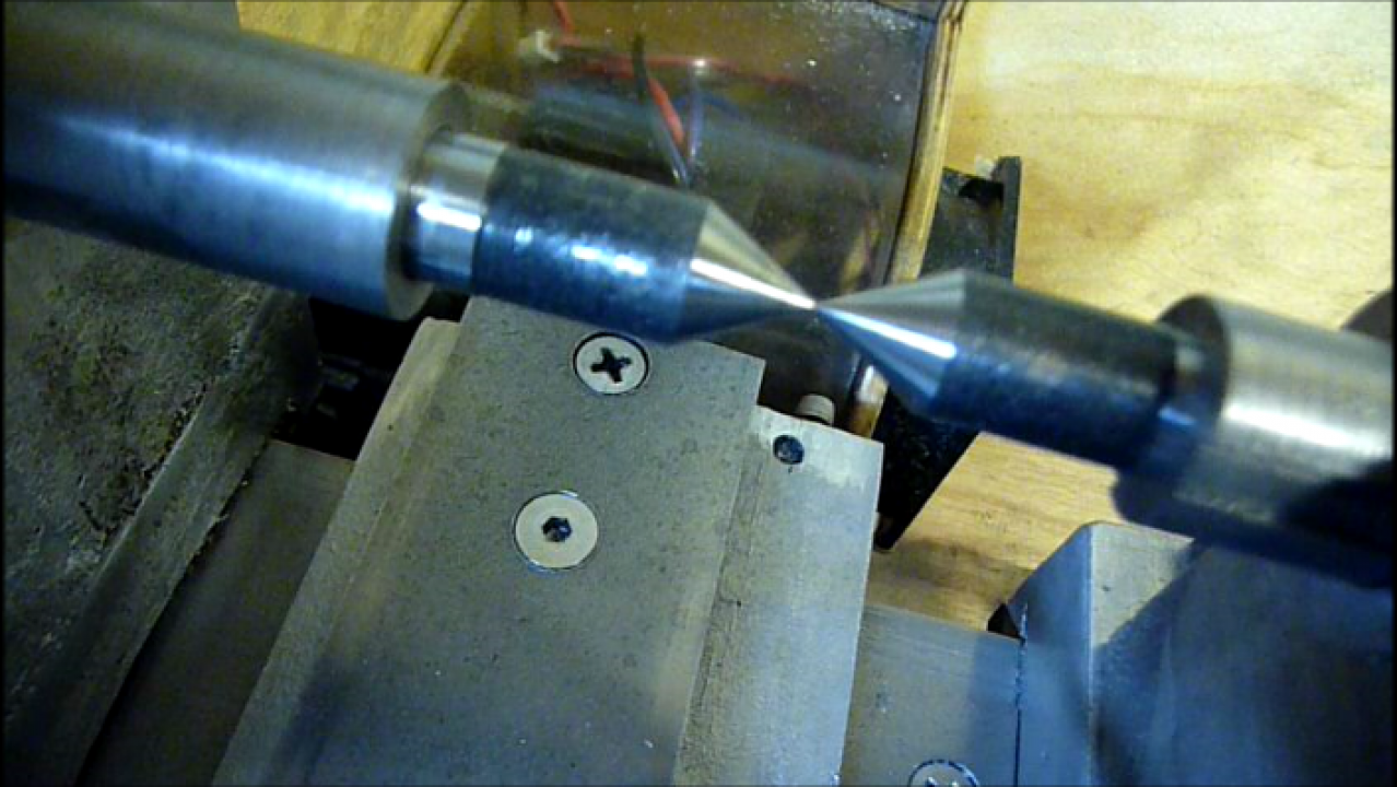
Photo of runout test on new MT1 dead center that I turned down:
That about finishes up the spindle. I’m currently working on cleaning up / commenting my PIC C18 code for the controller, and once done will hopefully get some files up for that if anyone is interested in that aspect of this project.
Cheers,
Morgan
Awesome work, I love seeing stuff like this! Metal casting has always appealed to me and I’d love to get into it at some point. Your lathe is looking great and seems to function quite well too. I’ve been kicking some ideas around in my head for making a lathe from scratch but without casting (using bar stock).
Great job! Your lathe runs smoother than my 3000# of cast iron. You sure have many talents and your videos done well, excellent editing! Do know how many you have in building your lathe. I have always been told that a lathe is the only machine capable of building it self, you certainly proved that!
Thanks Dale
nice and very accurate job
nice job!