Over the past few months I’ve had great success printing with my Box Frame Prusa i3, however there are some situations where the stock box frame i3 just won’t be able to produce decent prints in ABS without modification ( delamination of tall prints, corner curling on big prints, etc..). That being said, this post will go over some of the things I have done to my i3 in order to get better prints from it.
Video:
Upgrades to my Prusa i3 – 3d Printer
Heated Build Chamber
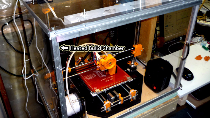
After much research it seemed like the solution to corner curling, and delamination, would be to maintain a consistent temperature around the print throughout the print job. Even though my printer had a heated bed, it was clear that things were cooler a few inches off the build surface.
The materials used to build the chamber for my printer were sourced locally and included flat, and angle, aluminum extrusions, optix 10″x18″ polycarbonate sheets, weather stripping, plenty of 6-32 machine screws ( with nuts and lock washers ), a cabinate door handle, and neodymium magnets. All in all, the build chamber came together quite well, though I have no formal plans for it, if you look at the photo above you can get an idea of how it is assembled. Realistically, it would have been a nice experiment to 3d print corner clips to connect all the plastic sides together, and see how it would come together that way – possibly how I will do it if I ever build another printer.

Having a build chamber is nice in that it provides plenty of surfaces for mounting accessories. The photo above shows how I was able to mount a camera and a light to the top of the chamber. A camera is essential if you are planning on running long prints such that you can do other things around the house and still monitor the job.
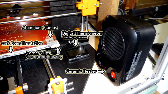
To heat the build chamber, I purchased a small ceramic heater, which will eventually automatically turn on and off to maintain a set temperature. At this point I primary use it to pre-heat the build chamber to 35 deg C, and then turn it off while the printer prints. You can see the heater that I used in the photo below as well as a digital thermometer which is visible on the camera.
Even with the heated build chamber, though reduced, corner curling with larger prints was still a problem. I continued to fumble around with temperature settings to no avail, when I realized that my build surface had a bit of a wiggle to it. Looking under the bed, the bearing holders for my build plate appeared to have been warped / melted a bit ( which caused the wiggle ), clearly something was off. I have an MK2b heated bed, and from what I read prior to setting up the printer – both sides could be facing up, however the flat surface was more ideal as it did not have the traces ( thus a smoother surface if you were not using glass ). That being said my bed was installed with the traces facing down, and what I found was the air temperature between my aluminum build plate, and the heated bed, was quite a bit higher than that above the print surface. I should have realized this before installing the heated bed, that the trace side was where the heat was being produced, so it should have been obvious then why I was having this issue. At any rate, the aluminum build plate was conducting all that heat and causing my bearing holders to warp. Also, since things were hotter below the build surface, possibly this was why corner curling was occurring, the build surface was cooler than I thought it was.
To fix this problem I ended up having to print new bearing holders for my Y-axis, added a foil wrapped piece of cork between the heated bed and the aluminum build plate ( you can see this in the photo above ), and then of course flipped over the heated bed having the traces facing up. It wasn’t too surprising that I now found my heated bed took much longer to get up to temperature from a cold start. Why? well before the bed was heating a small void between the heated bed and the aluminum build plate, and since the thermocouple was also mounted at the bottom of the heated bed, that area took much less time to heat up versus it attempting to heat up the free space above the heated bed.
Custom Aluminum Clamps for Heated Bed Glass
From the last photo you can see I’ve replaced the binder clips with some custom aluminum clamps. I machined these on my mini mill, and they are just the right dimensions that when fully tightened prevent any movement of the top glass. With the binder clips I was using, I found that I was still have to move the glass by hand, so this fixed that issue. Since I don’t tape my glass, and just use hair spray, I’m not too concerned with not being able to easily remove the glass from the heated bed.
One Hand Bed Leveling Clips
After a while trying to level the bed with both hands gets a bit tedious, especially at the back of the bed. You’ll notice in the last photo there are white clips at the corners of the aluminum build plate. There is a nut trapped in the bottom that allows me to quickly level the bed with one hand.
New Low Friction, Easy To Swap Spool Holder
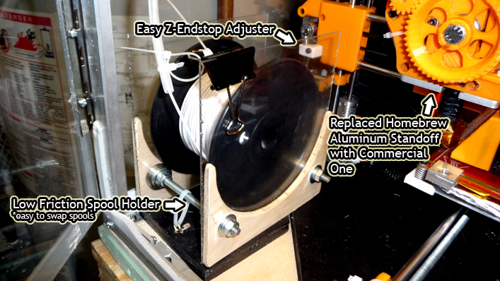
With the heated build chamber I was no longer able to use the spool holder that was mounted at the top of the box frame, however that spool holder was a bit of a pain when switching filament, as I would have to loosen up a bunch of nuts, etc… The new spool holder in the photo above basically allows me to quickly swap filament as I need to, as the spool just sits on 4 bearings and rotates very smoothly. To accommodate the new location of the spool I added in some plastic tubing from the spool to the extruder for the filament to be pulled through ( keeps things nice and neat in there ).
Adjustable Z-Endstop
In the prior photo you can also see there is a small white printout on the x-axis stepper motor mount. It’s basically a thumb screw that is aligned with the z-endstop. I can use this to quickly, and accurately adjust the z-endstop which is really convenient as I would have to loosen the z-endstop clamp and then push it up and down the rod by hand ( quite inaccurate ).
Remote Control of the 3D Printer with OctoPrint
It became quite apparent that with longer prints it was quite impractical to think that anyone would be able to sit in front of the printer for the whole job. That being said, safety is of the highest priority for me, and it was obvious that I would need some way to remotely control the printer, as well as the ability to see what was going on at any point in time.
My first attempt at operating the printer remotely was to setup ‘remote desktop’ between my windows desktop and my windows tablet. This worked to some extent, however if the connection ever dropped I was unable to get back onto the original session with my tablet, so this option was out.
My second attempt was with a free program called TightVNC. This program worked quite well, and also allowed me to gain access to the printer from my phone ( they have android and ios apps for free as well ). The main issue with this setup was that I needed to have my printer next to my primary desktop computer, and it really was taking up a lot of my desk space.
In comes OctoPrint and the Raspberry Pi. The Raspberry Pi is a small ‘computer’ that can run Linux, and a bunch of great people out there have put together some great, free, software that can take advantage of some of the benefits of having a fully blown portable computer the size of credit card – one piece of software being OctoPrint. The installation of the software was pretty painless, you basically download a distribution to the device’s SD card, and then start it up – everything you need is already loaded in, minus a few things to be configured, like the Wifi dongle and access to your home network.
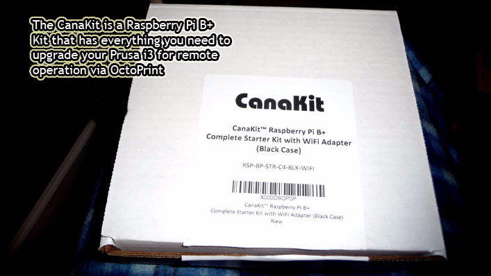
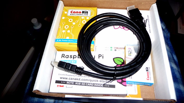
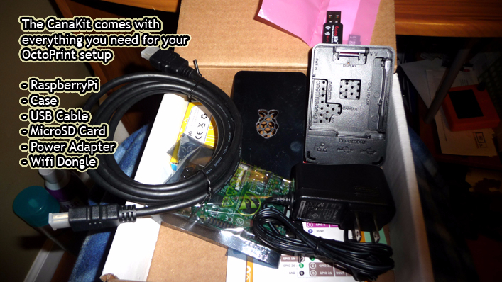
The photos above show the Raspberry Pi kit that I purchased. I’m quite pleased with the CanaKit, at $69, I got everything I needed including an 8gb sdcard, wifi dongle, case for the pi, ac adapter, great packaging, etc…
Results
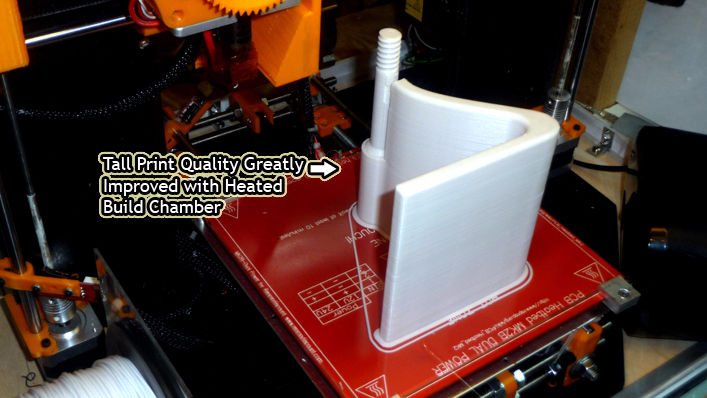
As you can see from the photo above, I’m getting pretty decent print quality with large & tall prints as of now.
Future Updates
I have a relay board that I’ll be hooking the build chamber’s light, and heater, up to which in turn will connect to the GPIO on the Raspberry Pi. I should be able to control those via OctoPrint which will make startup a lot easier ( won’t have to go down to the basement to preheat the chamber, etc… ).
Cheers,
Morgan
Very amazing. Are you tracking your costs to continue to compare to an equivalent commercial unit?
Steve, Morrisville, VT
Hey Steve, thanks for the comment! Totally appreciated.
I’ve been tracking the cost of the build, though I haven’t really paid much attention to the cost of commercial units, other than when I first started thinking about either buy, or building, a printer for myself. That being said I feel I’m still way cheaper than a commerically bought machine.
Here is the breakdown of my costs up to this point:
a. Box Frame parts ~$33
b. Prusa i3 parts – printed parts, electronics, rods, hardware, etc.. ~$450
c. Heated Build Chamber parts – aluminum, plastic sheets, hardware, magnets ~$100
d. Lasko #100 heater – $15.99
e. Digital Thermometer – $9.97
f. CanaKit ( for OctoPrint setup ) – $63.98
running total about: $672.94
that being said, if I was to do it again I would not have purchased the 12864 LCD Display Controller, as I don’t need it with OctoPrint – that would have saved about $20, so for me to build this again it would probably run around $650.
Cheers,
Morgan