In my opinion one of the key items lacking on the Gingery Lathe are the handwheel graduated collars that give you a rough idea of depth of cut, and/or distance traveled, etc… Obviously there are many ways that this can be solved, from gluing some measuring tap on a cylindrical blank to making some dial indicator clamps, etc… It became apparent that I could easily add spindle indexing capability to my lathe using my motor controller software, and I could also use the update with a dremel tool holder to do other interesting work on the lathe.
Video:
The Making Of The Spindle Lock, and a Demo Of The Spindle Indexer Update
The first item of business would be to design a Spindle Locking mechanism for the lathe. I found that with my pulley setup, when the motor was stopped ( without braking capability ) that the pulley would pull the spindle back in the reverse direction slightly. The spindle lock would allow me to preload the spindle in such a way that the pulley would not have this effect and instead would impart it’s force on the motor ( or countershaft ) spindle instead. Also, a locking mechanism would be required if I wanted to do any accurate work using a dremel tool, as the forces of that would most likely cause the spindle to rotate to some degree.
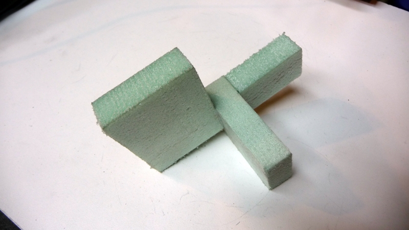
The Spindle Lock pattern was made from 1/2″ foam, and cast using the lost foam method. It turned out quite well, and I will mostly be using the lost foam method for most, if not all, of my future projects.
Spindle Lock Pattern:
Spindle Lock Rough Casting:

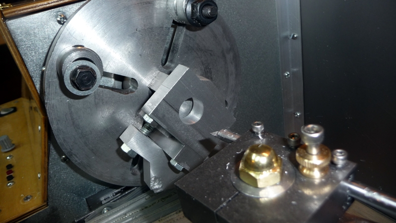
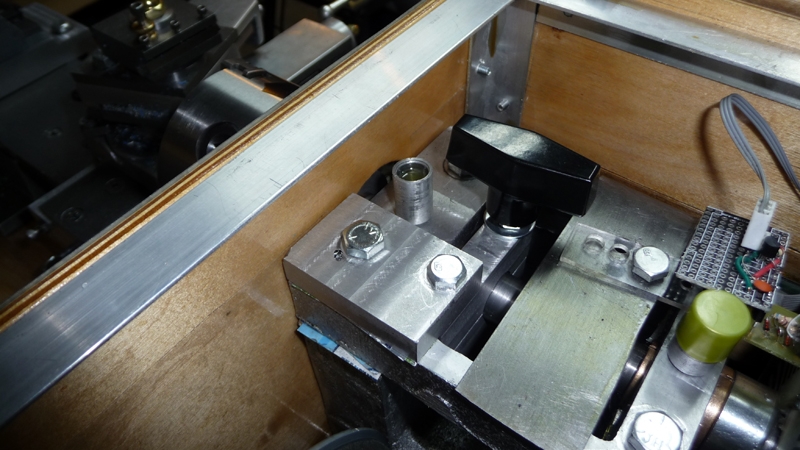
The spindle lock was cleaned up on my milling machine, and mounted to my lathe faceplate using the Gingery 2-jaw chuck in order to bore out the 3/4″ spindle hole. Obviously it took quite a bit of effort to get everything accurately measured and laid out on the part. The goal was to machine the part accurately enough such that it would not bind with the spindle in any which way when mounted such that when unclamped, it would not impeded the rotation of the spindle at all.
Spindle Lock Boring Operation Setup
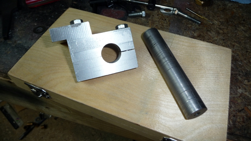
Spindle Lock Almost Done
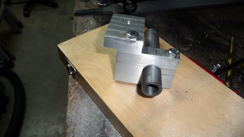
Initially I was just going to use the hex bold for clamping, but it became apparent that getting in the case with a wrench each time would end up being a pain in the you know what. Regardless I found a nice chunky knob at the local hardware store which works extremely well. I can lock down the spindle with finger pressure.
Spindle Lock Completed and Installed
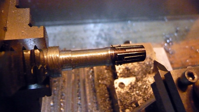
So, the main goal of the project was to facilitate the Spindle Indexing update. Everything worked as expected, and below is a photo of some scribe marks indexed on a pieces of aluminum.
What’s next? I had the desire to add a stepper motor to the leadscrew, however at this point I have some other projects I would like to complete, and possibly would also like to move on to making some sort of a 3d printer. Rest assured, I will most likely return to the lathe at some lather date in order to automate it further.
Cheers,
Morgan
Hi Morgan, Happy New Year! Good looking face plate and indexing tool set up, Gingery has a book, number 6, that shows how to build the dividing head and other related equipment. To me, it looks like it will be a fun project. There are some indexing tables as well as heads,(fair to good in quality) costs are pretty much across the board on the tool suppliers catalogs, Gingery built his for a hundred bucks and some change, I am sure the worm and gear are a bunch more than that now! Keep us posted!
Steve
Hey Steve,
Thanks for the reply, yes I purchased book #6 right off when I got the lathe book and there is a lot of neat information / accessories in there ( I used the plans from #6 to make the 2-jaw faceplate chuck, and setscrew chuck ) – my goal was to someday make gears in my home shop. At this point, time and money wise, I’ll most likely skip the dividing head build for now, though it does look interesting. The cost of the worm gear is a bit staggering, and I have other tools I would rather spend the money on. I really would like a 4-jaw chuck at this point, and will most likely buy one and machine the backplate as I did with the 3-jaw. I intended to build the gingery 4-jaw, but I have other projects I would really like to get to at this point. I feel that I could spend the rest of my life making things for my lathe
Cheers,
Morgan
Just a note! I saw a home made tool in Home Shop Machinsts magazine awhile back where a simple alignment tool was made for holding a metal stamp just for the purpose of stamping the numbers on round items such as indexing wheel/coller parts for a lathe or mill or fixture or, whatever! The tool was machined from bar stock and was made of steel, could be made of aluminum or brass as well. Once I find the back issue, I’ll send you the instruction for review. Made some adjustment to my lathe yesterday, took up the running slack in the carriage and it wasnt much, about .003. I have a gear train on the aprom, rack and gear assembly to move the carriage when the split nut is not engaged. My shop got really cold during the night and I was out there a while ago and tried to run the carrige back and forth, steel and aluminum cool at different rates, as I could not move the apron or carrige! Once the heat of the day and the shop heater warmed things up, all was well! I remember my Dad starting up all his machines in his shop at the start of the days machine work, sure made a difference in consistant tolerance! Hope all is well!
Regards;
Steve
Trying to find you and search for the info i had already got from you on the blog or online groups where i had found you a year ago; i found you, YEAH!
Have just bought a treadmill and tour it down to get the motor, drive board, control board and wiring. Was glad to get the one i did, only 25 bucks and all seems to work on it. The only thing i see that may be a problem and yet may not be is the motor is just 1.5 horse power, while most i’ve seen are 2hp.
Been searching your blog for any downloads you may have in any help i can get on wiring up the motor and maybe some programming and hardware i may need to get this thing off the ground. Got all my patterns made for the lathe and should not take me that long to pour them up. Finishing them a bit longer of course.
Are you on one of the google or yahoo groups in metal casting or gingery lathes that maybe you’ve already uploaded wiring diagrams and such i can go and download them from?
Sorry for this post on this blog, remove it need be. Just glad to find you again and get my motor and wanted to get started collecting info i’d need to get things rolling on this project. Please email me any info you have or let me know where i may download it.
Thanks, Rick.
Found the files and the downloads on the blog. Thanks, Rick.