With the motor controller & driver working as expected, it was time to cast, bore and mount the headstock. I initially wanted to design the headstock for roller bearings, but quickly realized that without the proper tools to bore a fairly large hole accurately that would be out of the question. I instead fell back on the design suggested in ‘Dave Gingery – Metal Lathe‘ book which calls for bronze bearings. When designing the pattern for the headstock, the design was based on the book, but wall thicknesses increased, and updates were made to the bearing caps / bearing supports to make the overall design more rigid. Being a fairly large pattern, a deeper 12×12 drag was made to support the pattern. It was expected that this pattern would require a full pot of metal like the lathe bed, so the possibility of failure on the up-scaled version was definitely a possibility.
Molding the Headstock:
 a. The headstock box slide wear pads, clamp surfaces are bedded into a false drag initially, then the cope is put on the top and parting dust dusted on. This is then rammed up with molding sand, and then the flask is flipped over. The false drag is pulled off and discarded, next photo shows what you would see.
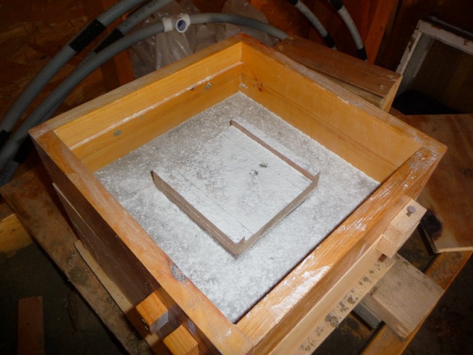 b. After removing the false drag, you see the headstock box slide / wear pads / clamp surfaces. The drag is installed again and parting dust dusted on. The drag is then rammed up with molding sand, and the flask flipped back over. The next photos shows the sprue and riser holes cut.
 c. I use copper pipe with edge sharpened to cut the sprue and riser. I have a small spoon that I use to cut a funnel around the pipe while it is still inserted into the molding sand. chalk works well to mark where you want to cut the sprue and riser before you get to this point. Next photo shows the flask opened up.
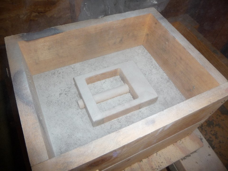
 d. The flask is opened up, and the gates are cut from sprue and riser to the pattern. The pattern is removed and this is what you would see. Close up the flask and you are ready to pour some metal into the mold.
Molding the Headstock Bearing Clamp:
 a. A false drag is used – the pattern is pushed into the false drag, and the cope installed and parting dust dusted. This is the view in the photo now. Next the cope is rammed up with sand, then the flask flipped over, and opened up. The false drag is shaken out, and then re-installed. Parting dust dusted on, and then drag rammed up again. The flask is then flipped over, sprue and riser cut, and then flask opened up. Next photo shows the opened flask with gates cut from riser & sprue to pattern.
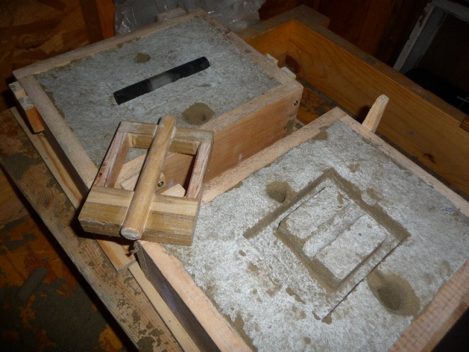 b. A steel core is used to create a the bore in the bearing clamps. The steel core is waxed for easy removal.
With the molds ready to go, it was time to fire up the furnace. Here are some photos of the melt about ready ( still need to skim the dross ):
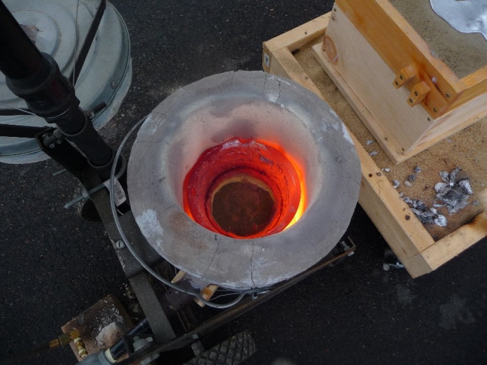

* look for link to the video of this at the bottom of this post to see me pouring the metal…
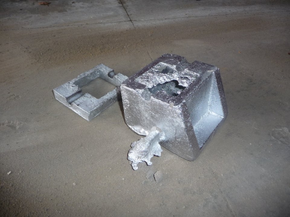
Everything went well up to this point, however when pouring the headstock mold it became evident that I didn’t have enough metal ( similar to what happened with my initial bed pattern ). It was clear that I would have to trim down the pattern a bit to make it work. The headstock bearing clamp casting came out quite nice.
Photos of the failed headstock casting:

Photos of the successful headstock bearing clamp casting:
Since I didn’t want to make another headstock pattern from scratch, I ended up trying to cut out some of the additional structural material that I added to the original design in the Gingery Lathe Book. As you can see from the failed casting photo above, my pattern was more of a ‘box’ than the base with two verticals like the book suggests. I ended up removing the front and back walls ( to match the book pattern ), and figured that my clamp ( which was one part, versus two ) would provide the additional structural support to the bearing supports.
The second attempt headstock pattern was molded in a similar fashion to what I described above, and the furnace started up for the pour.
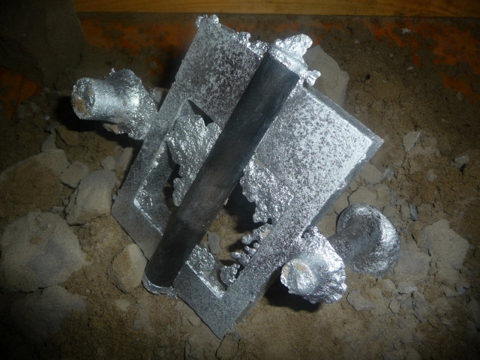
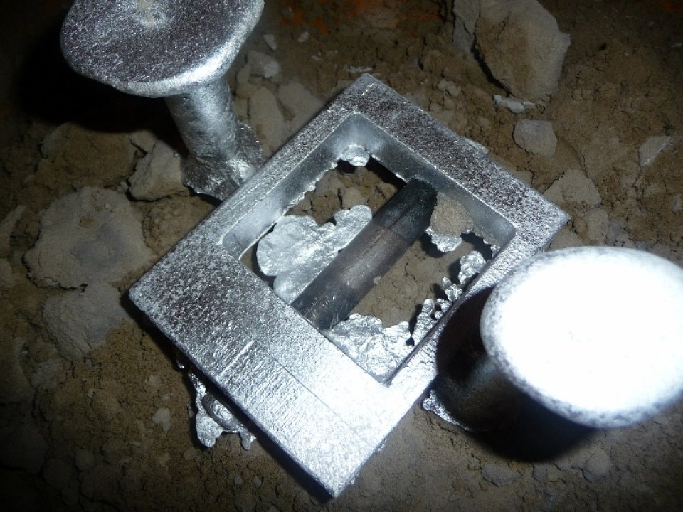
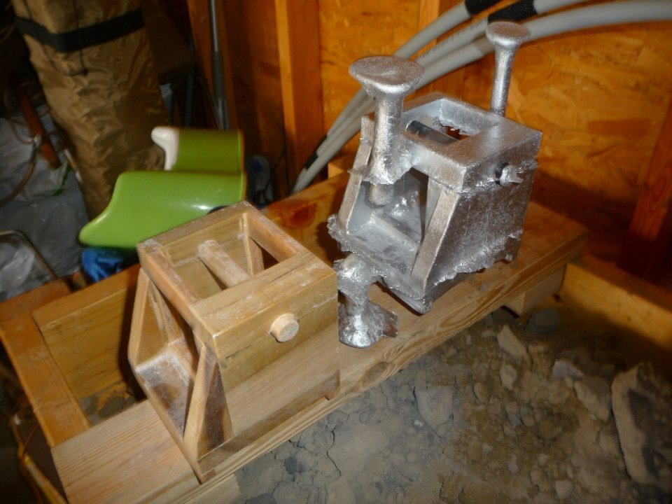
Photos of the successful headstock casting:
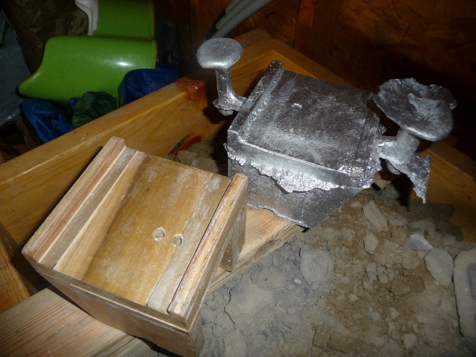
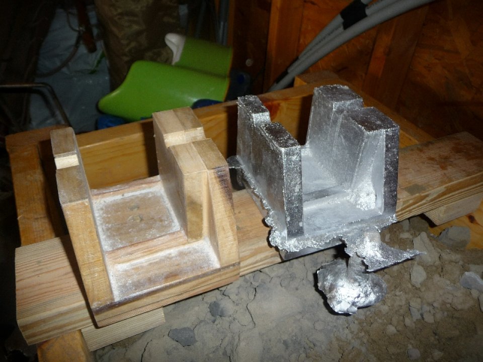
Photo of headstock with clamp on top:
I still needed a full pot of metal to get the headstock casting cast, and I decided it would be a good idea to weigh the rough casting to get an idea of the maximum weight that I can cast in aluminum with my current setup.

The weight came out to 6.1lbs 2oz.
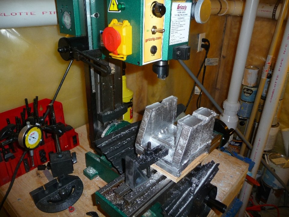
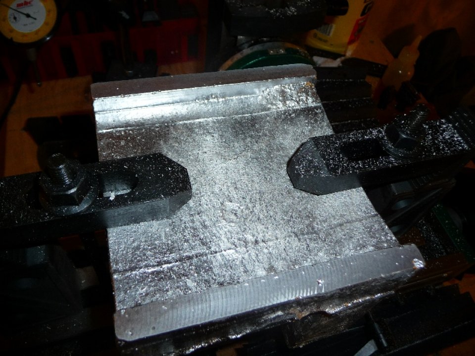
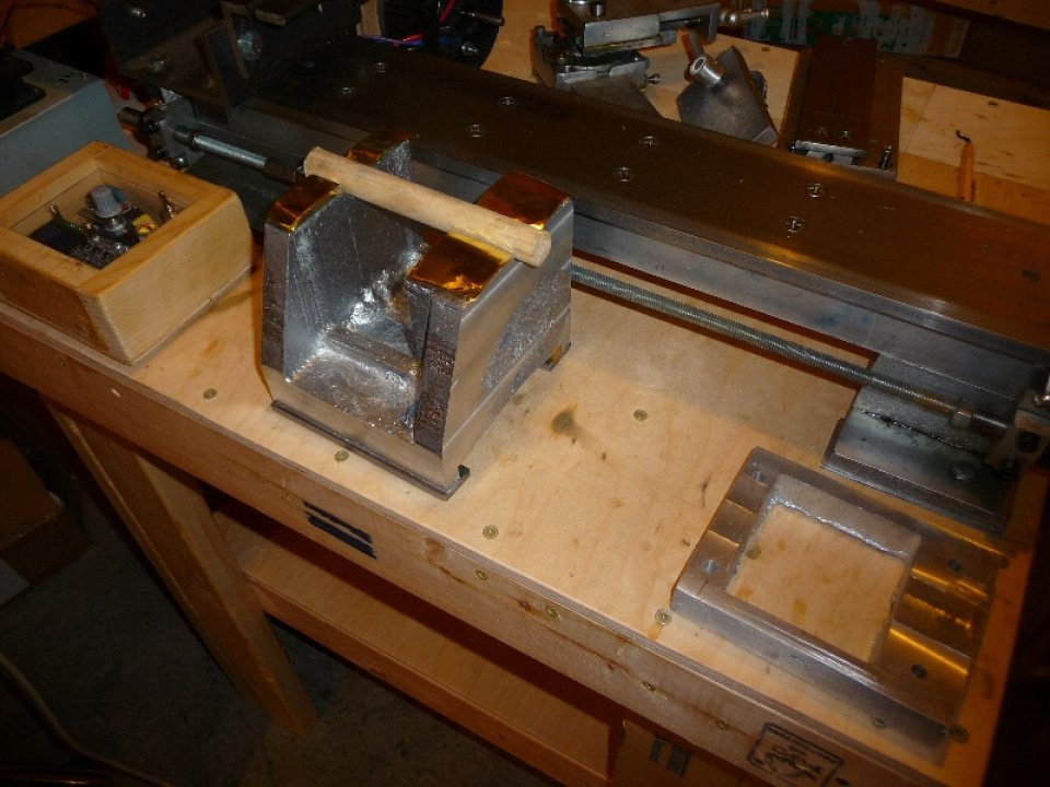
With both the headstock and headstock clamp patterns cast, it was time to cleanup the rough castings. Typically this would involve much work with a mill file, and then a 14″ lathe file, however in 2011 my awesome wife purchased me a grizzly mini mill, and this was going to be the first project I’d really get to use the mill on. I was excited to not have to do so much filing, however I was still planning on hand scraping all bearing surfaces.
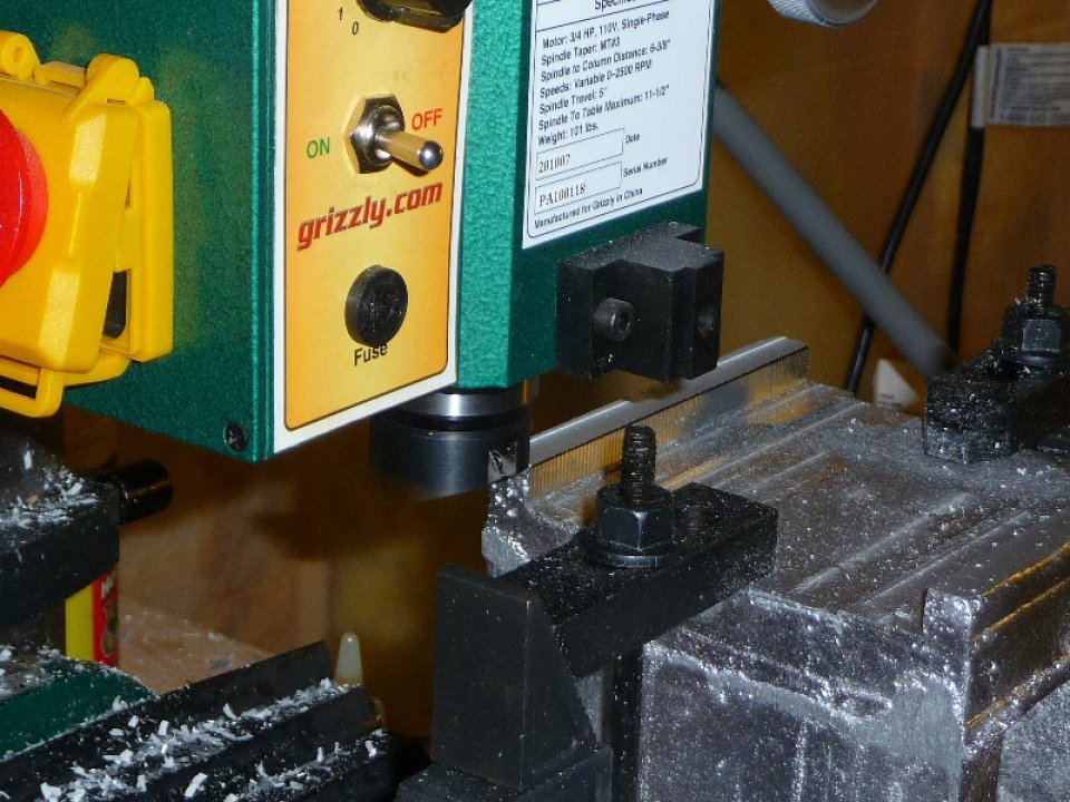
Due to the odd / large size of the headstock, I ended up purchasing a clamping kit which worked well. The headstock clamp surfaces ( for the box slide ) and top wear pads were fly cut, and the side wear pads were cut with an end mill.
Photos of me finishing up the headstock on the mill:

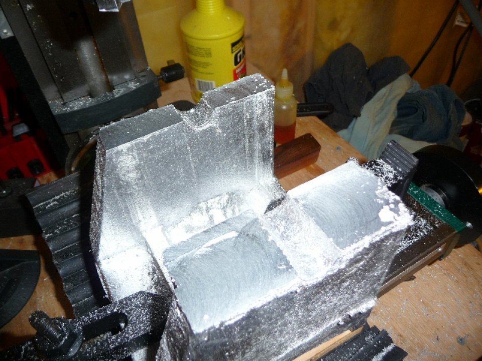

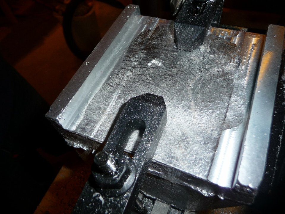

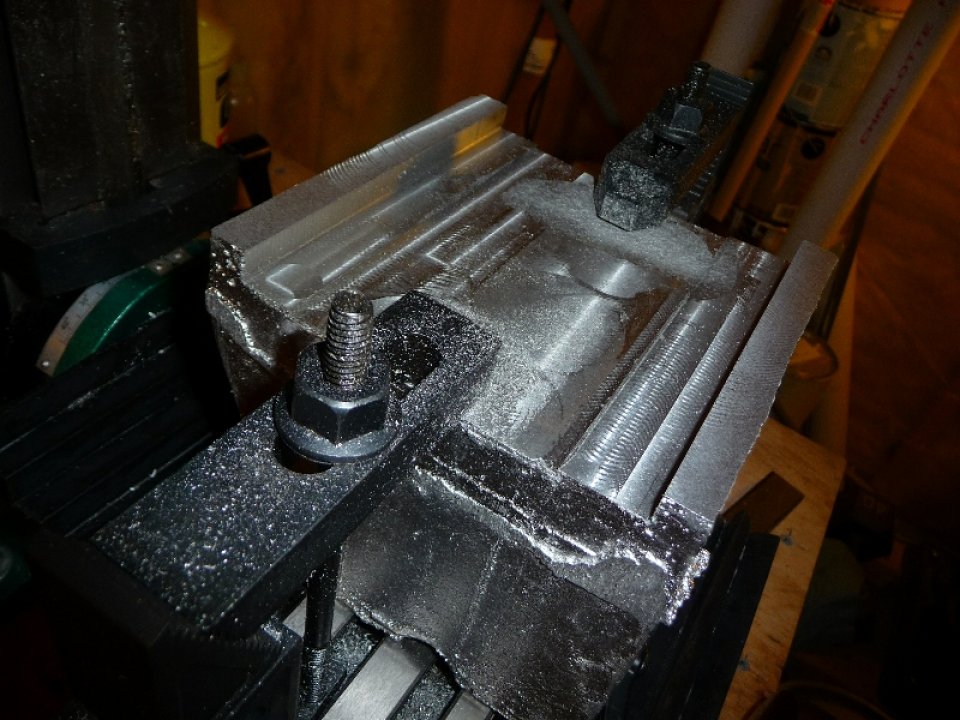
With the headstock cleaned up I proceeded to test the box slide prior to hand scraping the wear pads and clamp surfaces.
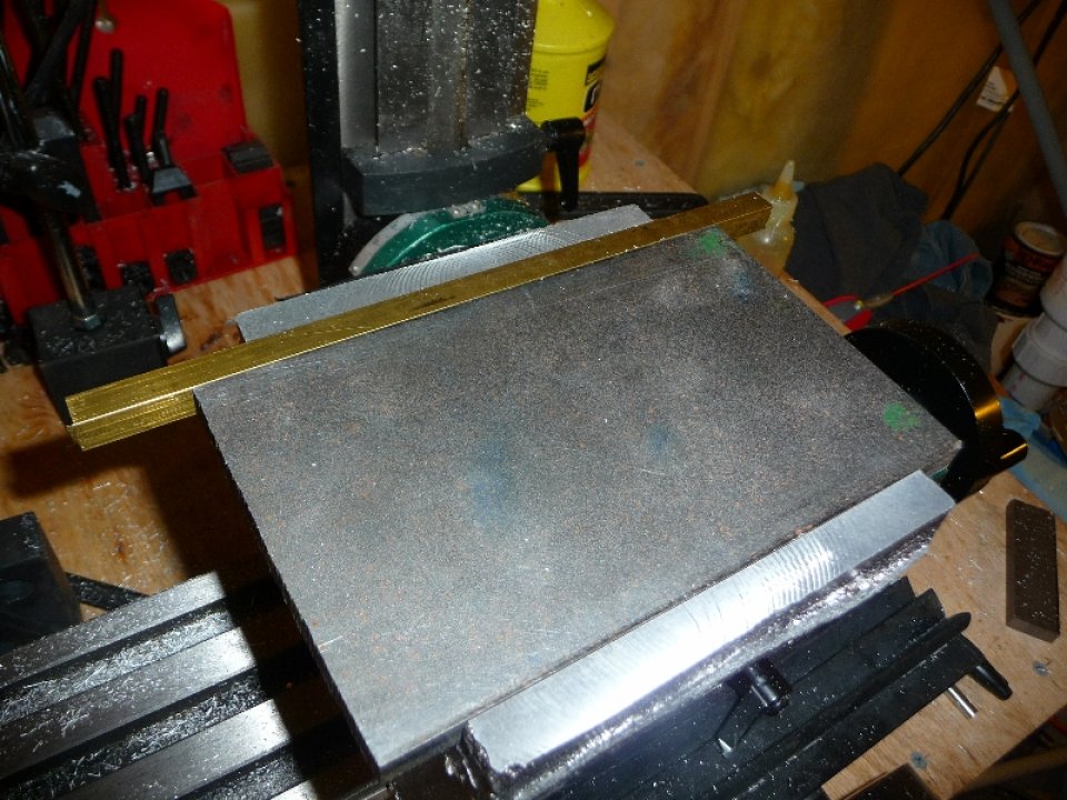
With the headstock box slide gib and test plate sliding smoothly in the box slide, it was time to install the box slide clamps. This was done in a similar fashion to the carriage casting – shims used to create a smooth / tight fit on the ways.
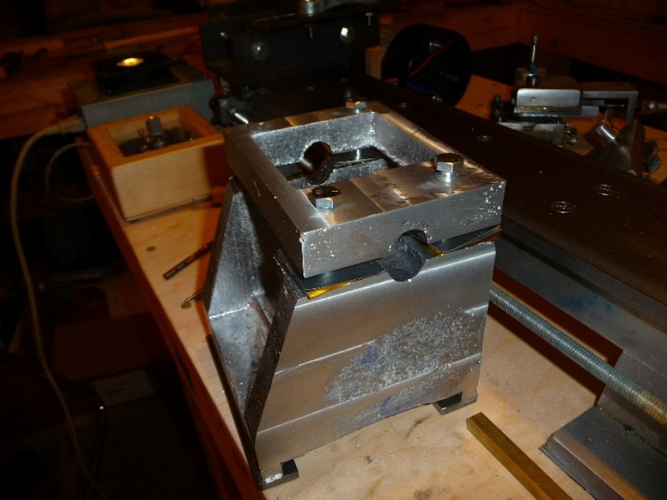
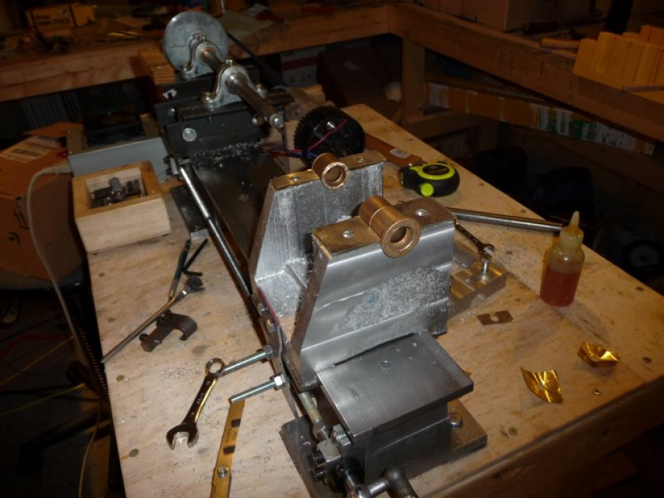
With the headstock box slide completed, it was time to fit the headstock bearing clamp to the headstock. A 3/4″ dowel was used to align the clamp to the headstock, while the bolt holes were drilled. Shims were used between the clamp and headstock to allow for adjustability in the event that the spindle bore was cut oversized, or to adjust for wear in the bronze bearings down the road.
Photos of the headstock clamp being fit to the headstock:

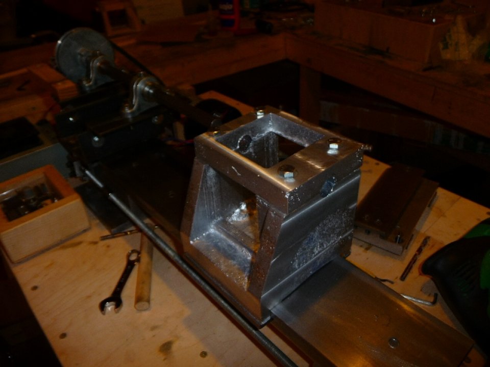
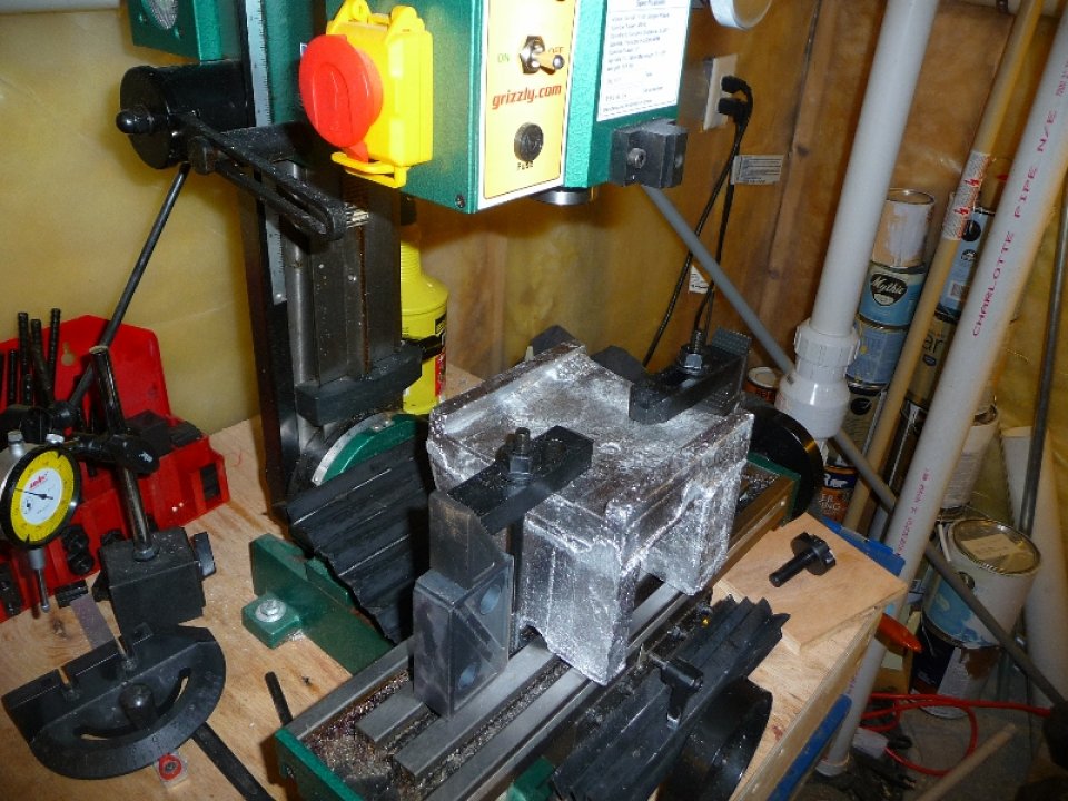
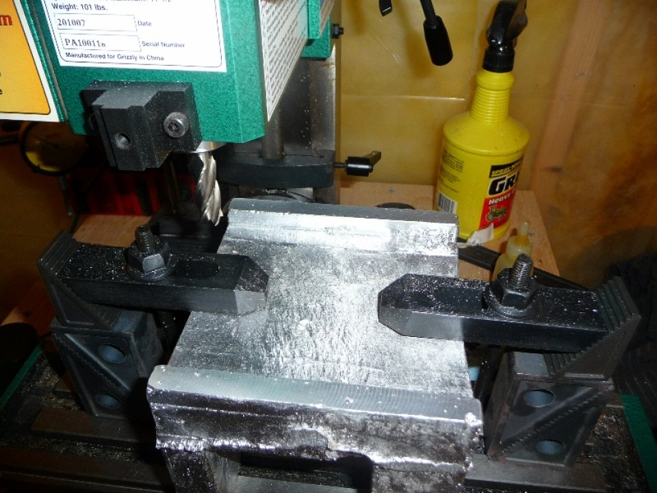
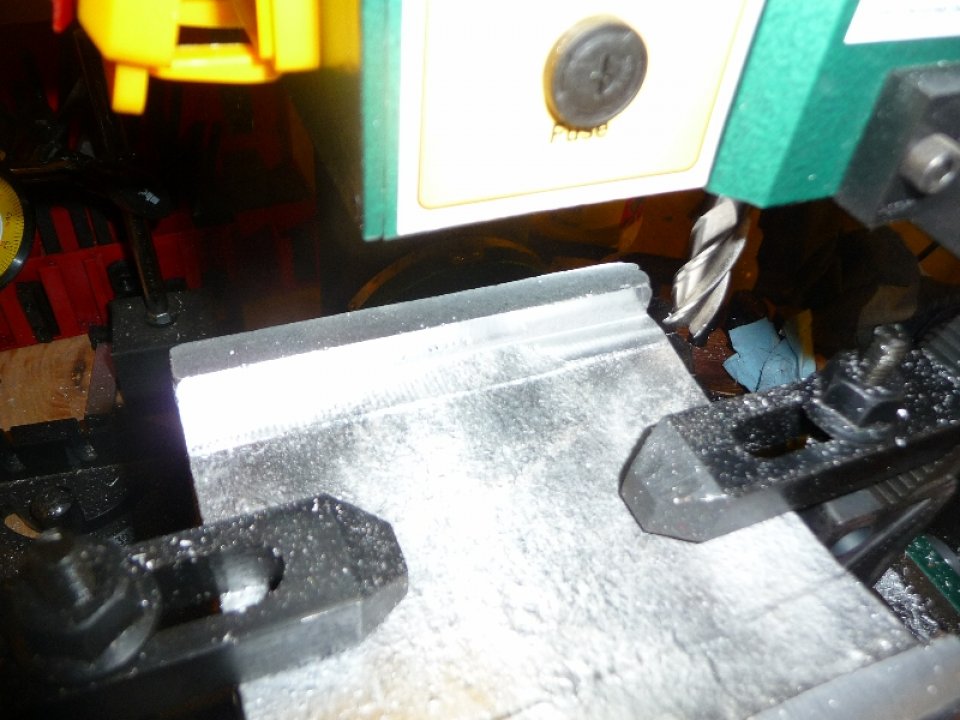
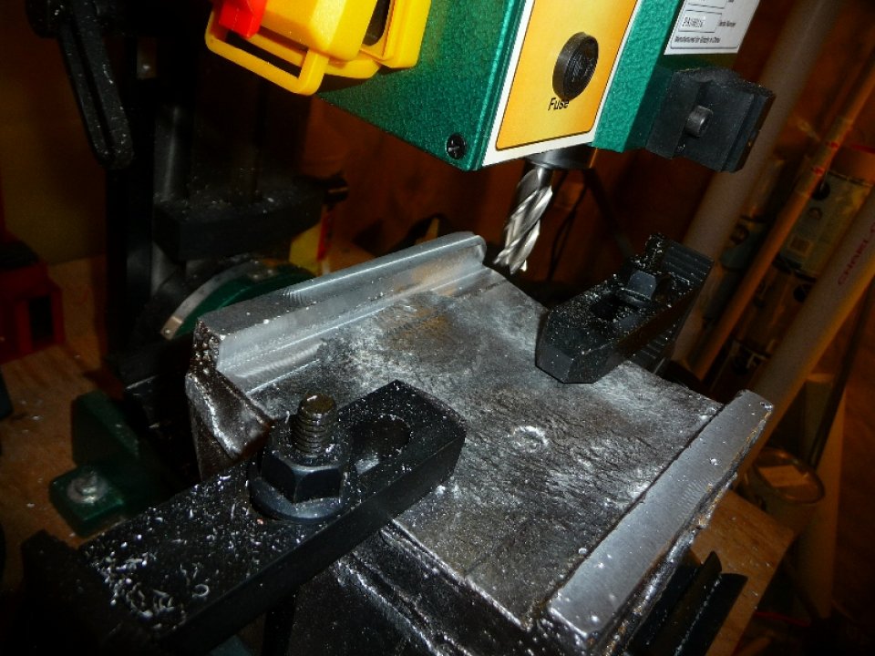
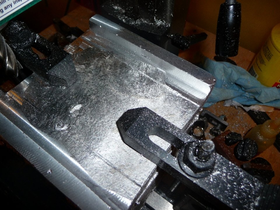
At this point it was time to prepare the headstock for the boring operation. Since there is no lathe to cut the spindle bore, and I don’t have a boring bar for the mill, the method used in the Gingery Lathe Book was used. The temporary headstock was adjusted such that the boring bar was centered on the headstock spindle bore ( starting hole from casting ). A temporary apron was created for the headstock such that the leadscrew could drive the headstock along the ways. Effectively the motor will drive the boring bar, and the headstock will be moved onto the cutter.
Photos of the Temporary Apron being made & installed:
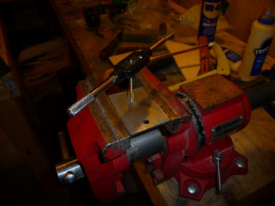
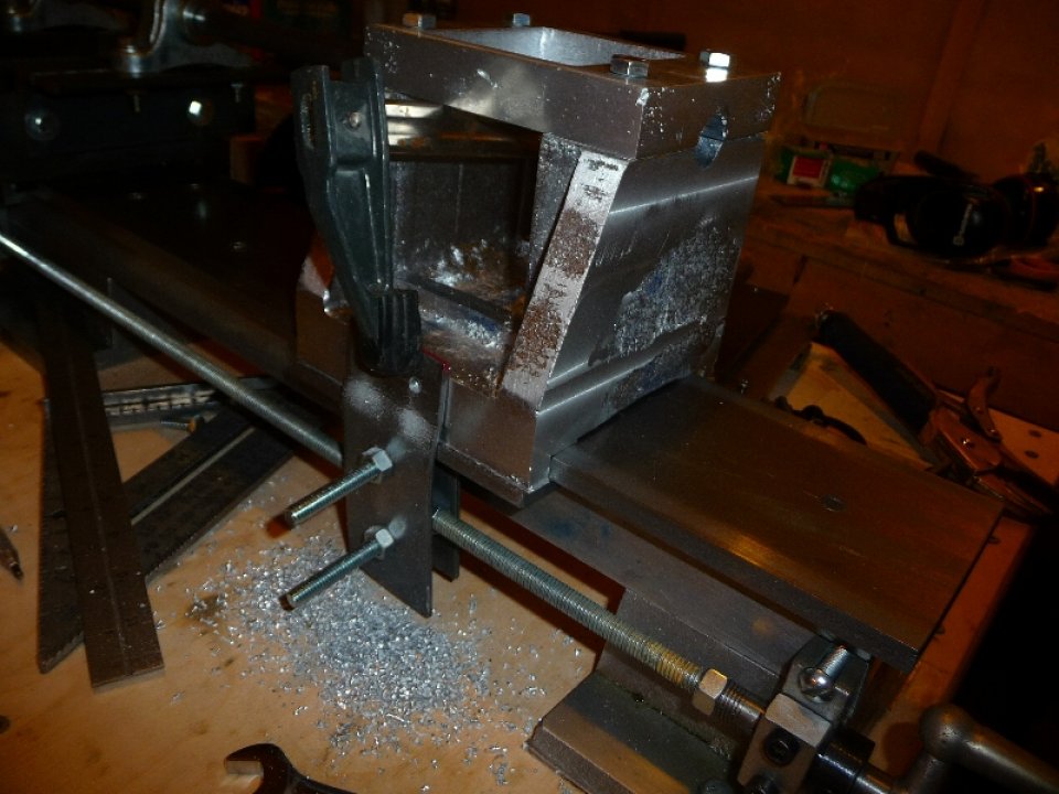
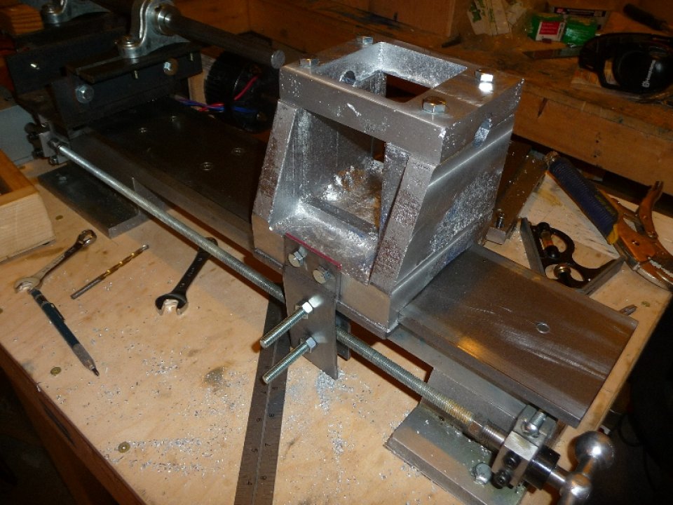
Photo of boring setup:
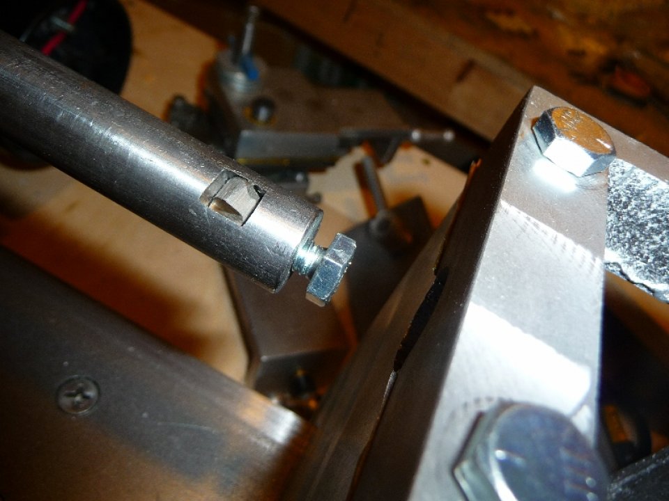
The boring bar was made from 5/8 round CRS stock. A 1/4″ square hole was cut at the end, and a 1/4-20 threaded hole created at the end for a set screw to lock the cutter. The cutter was ground per the Gingery Lathe Book description.
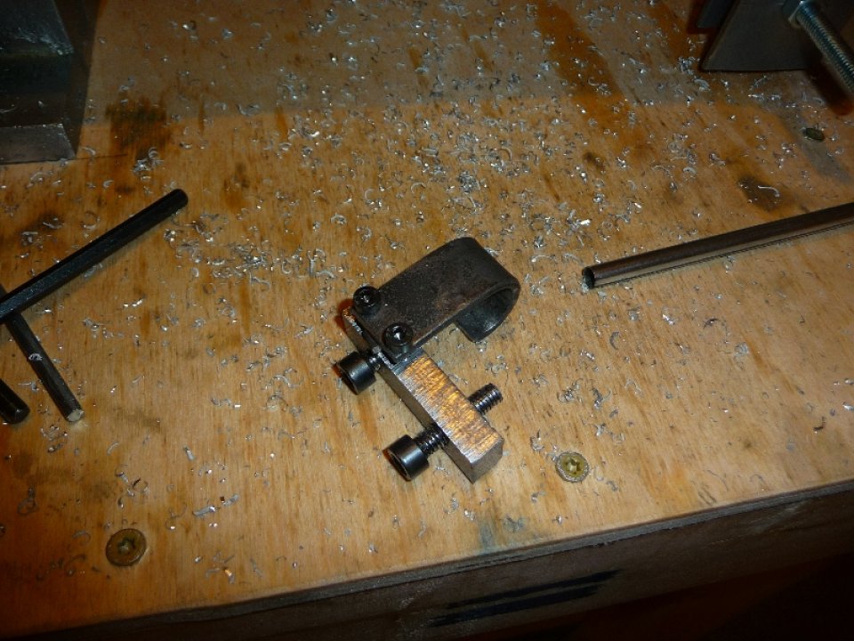
In order to accurately cut the bore, a tool to set the cutting radius was created as described in the book. The tool locks on the boring bar, and a feeler gauge is used to increase the cutting radius by some small amount.
Photo of boring bar adjustment tool:
I don’t have any photos of the boring operation, but definitely checkout the video I created for this, as there is a section of me boring the headstock.
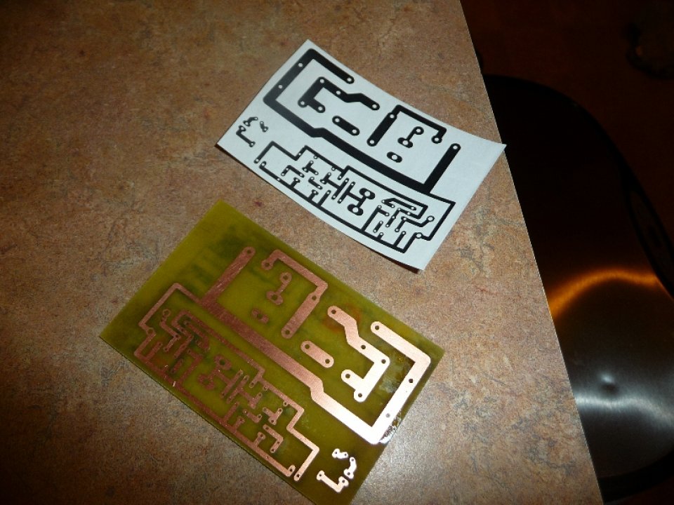
Half way through the boring operation, I was probably feeding the headstock a bit too fast and ended up blowing the driver’s mosfet. After replacing, and blowing a few more it became evident that I needed to re-design the driver electronics. I was planning on creating a PCB for the driver anyways, so it was a good chance to do some PCB etching. The main issue I believe was that the with the 30khz PWM frequency, and the mosfet’s gate resistor / capacitance – the mosfet was not turning on and off fast enough, and thus too much power flowing through when the duty cycle increased to compensate for my higher feed rate ( to maintain speed ).
Photos of the new driver PCB:
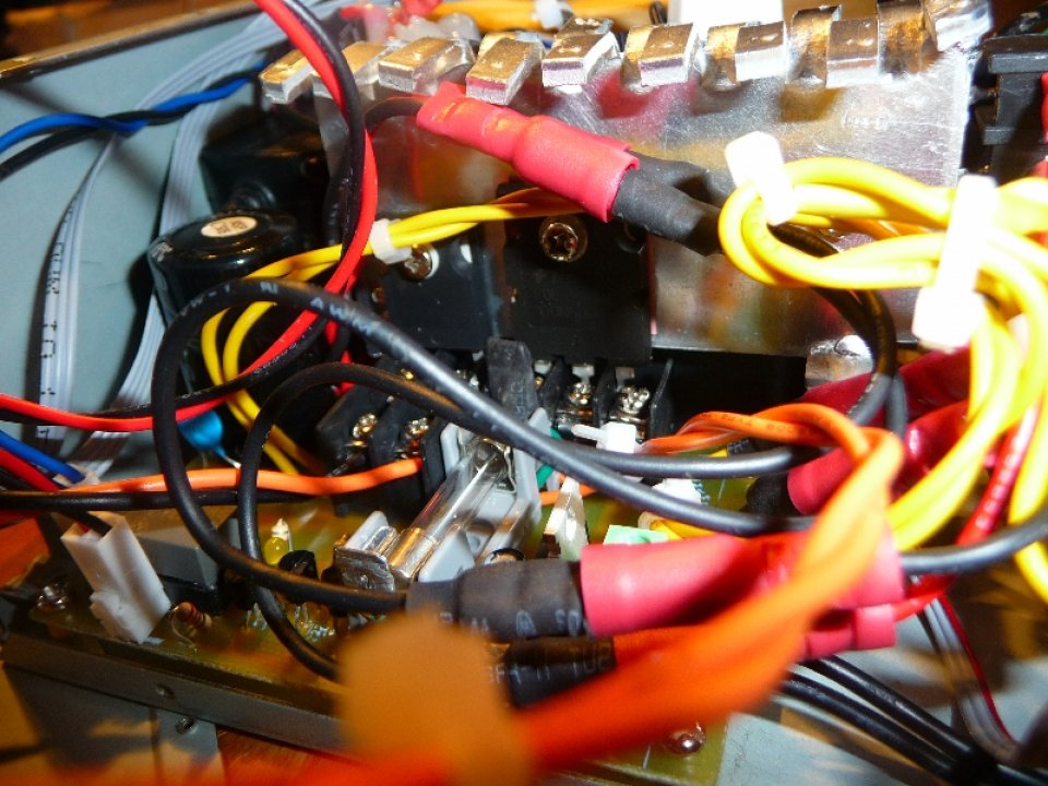
Photos of the inside of the new driver:

I like to test everything out with a small 12vdc motor before driving the actual motor with 160vdc. Here is a photo of my test setup:
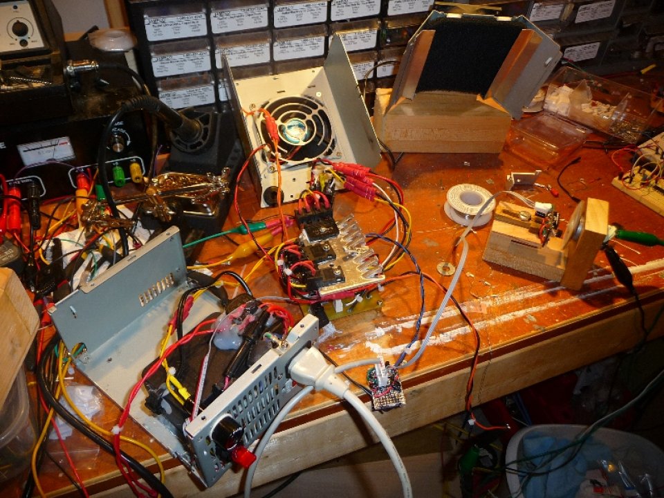
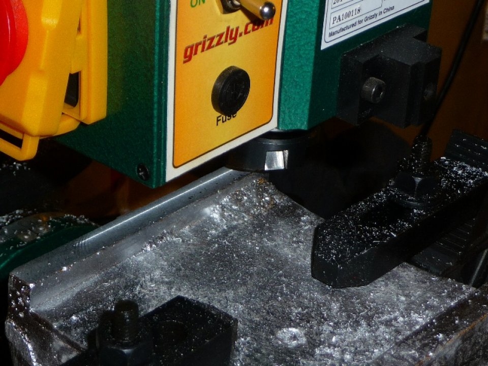
Everything tested great, and it was time to get back to boring the headstock. I was within 0.025″ of the bore size, and it took 3 more passes to complete the bore. I pushed the new driver as hard as I could to ensure that the update corrected what issues I was seeing with my original driver. It ran perfectly, and haven’t blown another mosfet since.
I ended up boring the hole slightly over-sized ( not intended, though accurately reading a bore diameter with a cheap digital caliper is quite difficult ), by about 0.002″, and had to remove a couple 0.001 brass shims from the clamp in order to bear down on the headstock bearings. Instead of using temporary bearings like the book suggests, I decided to skip to the end of the book and install the final bearings right away. To accommodate the temporary 5/8″ spindle, I installed a 5/8″ sleeve bearing inside the 3/4″ flange bearing. When I have a proper spindle turned for the lathe, I’ll remove the 5/8″ sleeve bearing.
Photos of of the bearings being installed:


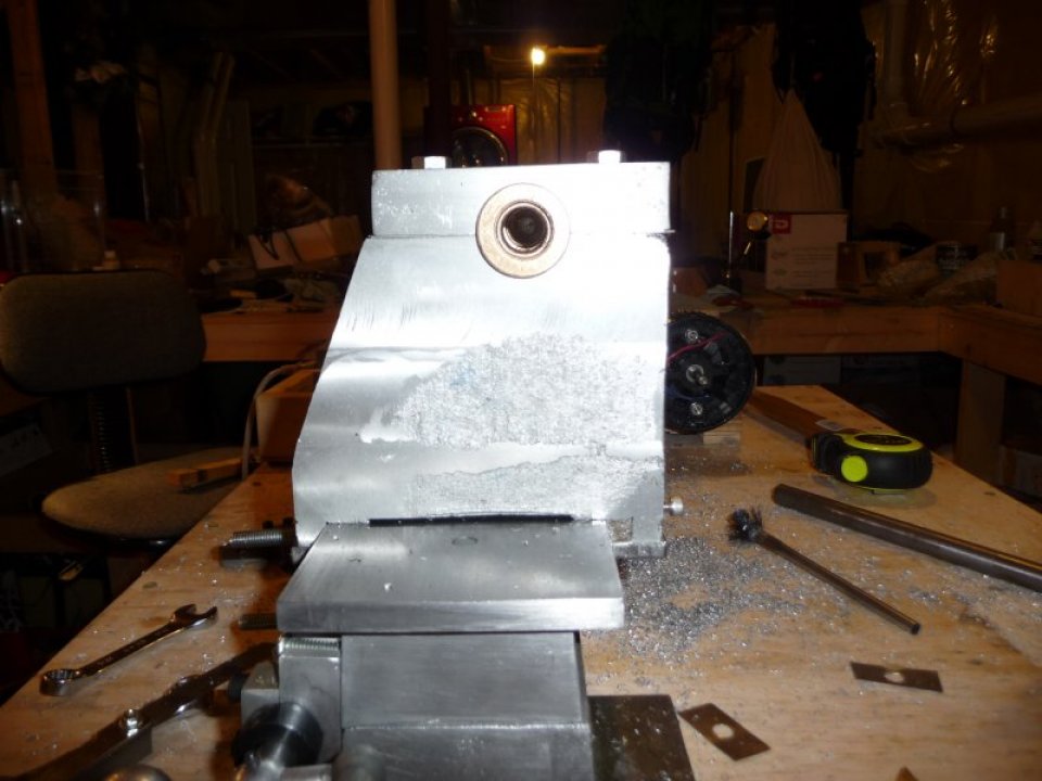
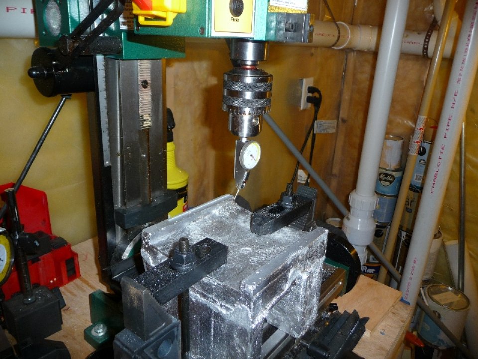
Two 1/4″ holes were drilled through the bearing clamp in order to provide an oil well for the bearings to stay lubricated. Cotton was stuffed in the holes to keep debris out of the holes. I used the temporary spindle / boring bar to test the headstock bearings, and they worked perfectly – nice smooth rotation.
Photo of the Headstock in it’s mounting position with boring bar installed:
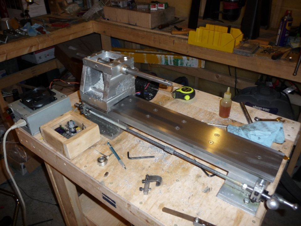
With the headstock pretty much done, it was time to mount it to the bed in it’s permanent position. In order to do this, the ways had to be removed from the bed, and it’s mounting holes used as a template for the headstock mounting holes. With the headstock clamped to the far left of the ways, the mounting holes were extended into the headstock with a hand drill, and tapped for 3/8-16 studs. For photos of the process of mounting the headstock, checkout the accompanying video.
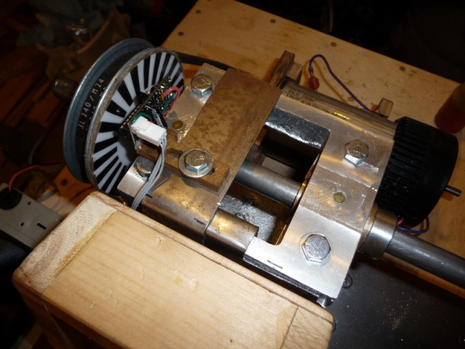
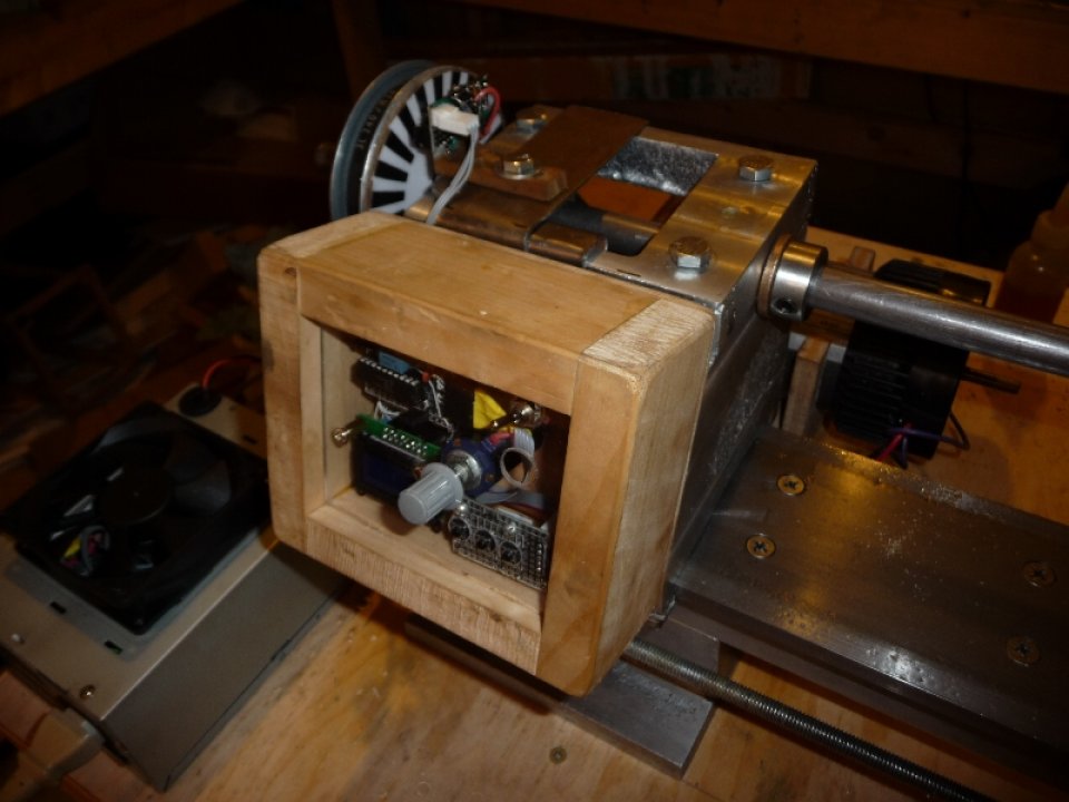
With the headstock bolted to the lathe, I needed to re-position the motor, as the temporary headstock extended beyond the ways quite a bit. At some point I intend to make a cover / case for the lathe, as it seems rather unsafe running a machine with exposed belts. That being said, I wanted everything to be as compact as possible. I moved the spindle pulley all the way to the headstock casting, and flipped the pulley around such that the encoder wheel was facing the headstock. The motor was re-positioned such that the belt would run true. I used heavy gauge sheet metal to fashion a mount for the my control box, and optical detector, which was now facing the encoder wheel from the headstock end.
Photos of the current lathe setup:
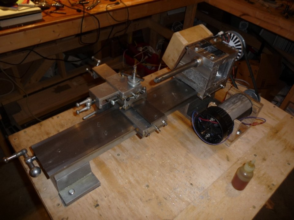

With everything setup for it’s final position on the table, I turned the controller on to ensure that everything still worked. With everything working as expected and the headstock completed, my next operation will be grinding down a left handled lathe tool bit such that I can turn down 3″ of the temporary spindle to 1/2″. I will be using the 1/2″ nub as an arbor for the leadscrew automatic drive pulleys ( to be cast ). Once that is done, I’ll start working on the tailstock.
For the accompanying video go here:
My Gingery Lathe Headstock »
For additional information / discussion on the Gingery Lathe / Gingery Machines, checkout the: Gingery Machines Yahoo Group »
Cheers,
Morgan
I am totally blown away with your lathe project………that drive is really nice!! I just found your web site and will be watching your progress. I’m going to build mine some times this fall maybe. Would really like to use a DC motor drive system like yours. Do you have the schematic for you drive board online? What kind of motor are you using? Can they be found on the cheap …….. maybe reaped off of something that’s easy to fine?
Also……..are you not using any cutting fluid on your cuts……….looks like it would cut 10 times better with just a couple drops of cutting fluid on each pass!! Also try just one drop of cutting fluid on each hacksaw cut you make on aluminum and you will need less than half the elbow grease to power it threw the cut. Try it and you will never go back to DRY cutting again. Have fun……..will be watching your progress………….Rick
My question is how to make the molding sand in the house. Your weight is great
Hey Thanks for the comment.
If you take a look here, I give more details about my greensand:
http://morgandemers.com/?p=153
There is also tons of good information here about homebrew greensand & casting:
http://foundry101.com/archive.htm
I’m planning on making a smaller propane furnace, and doing some lost foam casting. I’ll most likely do a full set of videos on that so stay tuned.
Cheers,
Morgan
Thank you from behind the good news.
Your website is good for me to create my new concepts.
Zbigniew
With your wider bed ways, did you keep Gingery’s headstock bore offset at the same 1.5″ from the backside of the headstock casting?
On my headstock, the bore is 2″ in from the backside.