With my foundry setup, and some experience casting basic patterns under my belt, it was time for me to start work on the Gingery Lathe. At this point in time I had read quite a bit from the Gingery Machines Yahoo Group, and wanted to try and upscale the design a bit. In book #2 the design calls for ways made out of 1/4″ CRS that is 3″ wide. I decided to use 4″ wide – 3/8″ thick CRS plate, and upscale the bed casting to match. I also wanted to increase the wall thickness of the bed casting, and the number of cross braces in order to reduce any twisting that could occur. The book already suggests that the original bed pattern would require the full capacity of the foundry from book #1, so it was my hope that my slightly larger furnace would be able to handle a bit more metal to accommodate the larger pattern.
The first attempt bed pattern had an exterior wall thickness of 1/2″ ( book calls for 1/4″ ) with the cross braces, and top, at 1/4″. The book has 3 cross braces, and I increased it to 5. The length of the bed remained at 24 3/8″, but I increased the width to 3″ ( book calls for 2″ ) to accommodate the 4″ wide ways.
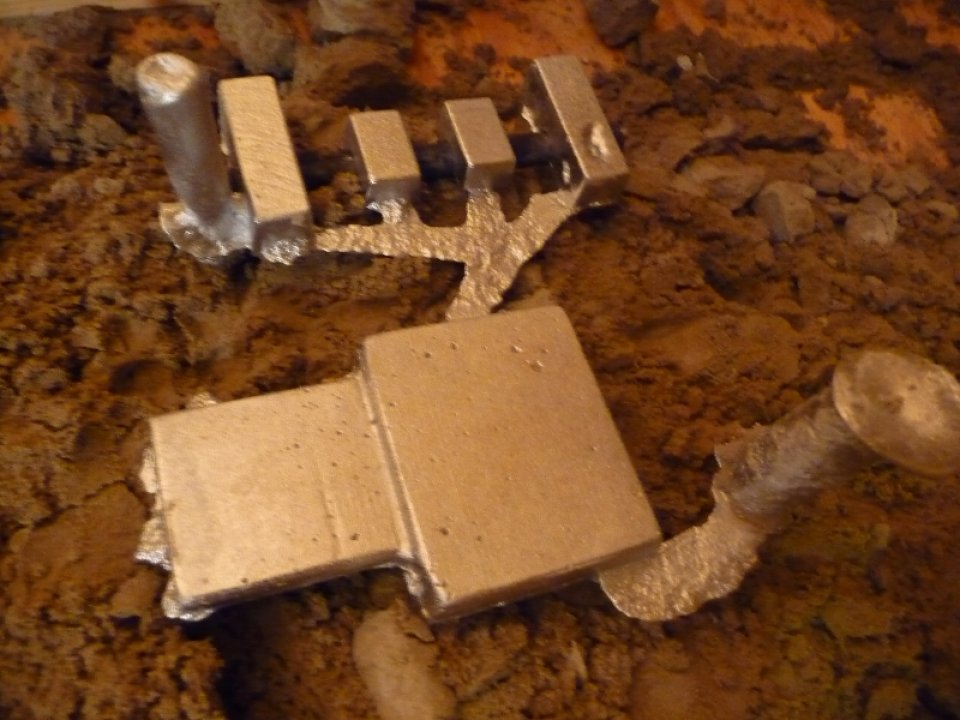
So everything was all set to go. It took a few attempts at extracting the pattern from the sand mold; it was hard to lift the pattern and ensure that all the cores remained undisturbed. I finally got it set after the 3rd or 4th attempt, and was ready to fire up the furnace and pour some metal. I got the 1.5qt cast iron pot brimming, and poured into the mold. Unfortunately I didn’t have enough metal ![]()
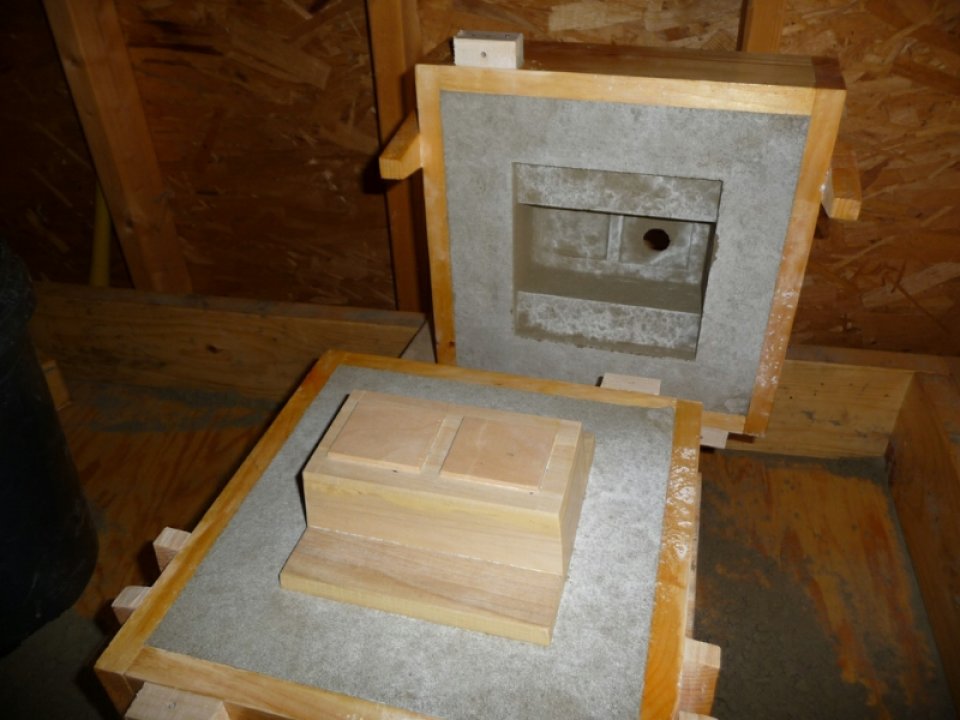
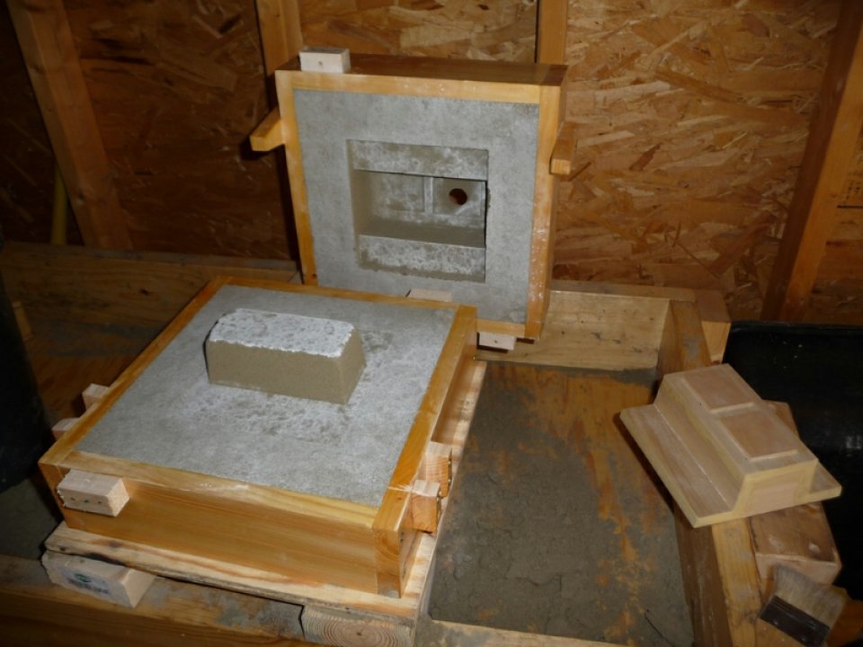
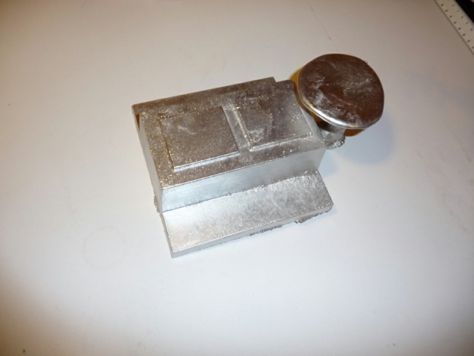
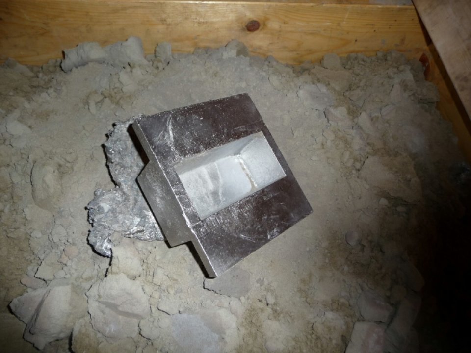
Photos of the first attempt after opening the flask:
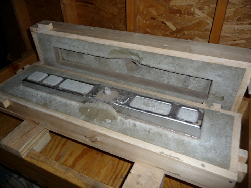
As you can see from the photos I didn’t have a chance with this design, as it didn’t even get to fill in the top of the casting at all. So back to the drawing board. I still wanted to maintain the larger width as I had already ordered the 4″ wide CRS for the ways. I liked the idea of having more cross braces, so those would stay. I believed that if I reduced the exterior walls from 1/2″ to 1/4″ that would leave me with enough additional metal to at least fill all the way to the top of the casting.
Getting the pattern out of the mold this time around went a bit smoother ( I’m thinking only 2 attempts looking back ), and I was excited to try and get this part out of the way ( at least casting wise ).
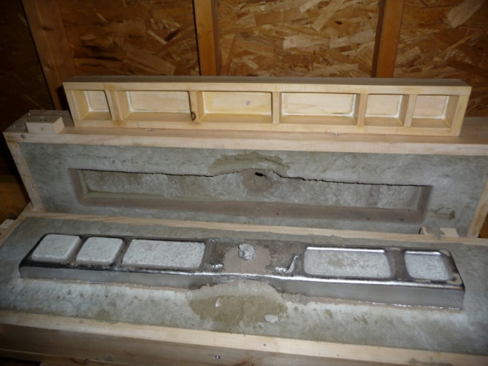
Photos of Sand Mold + Pattern:

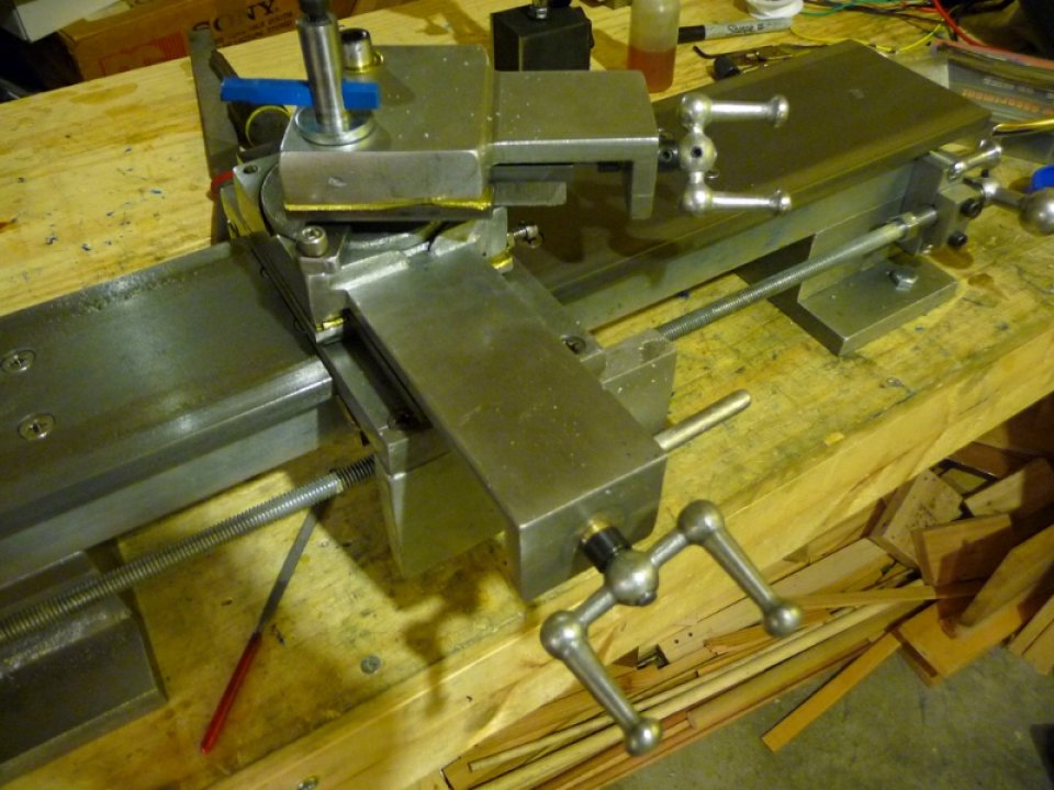
Photo of the setup for the downsized larger bed:

From the setup photo above you can get an idea of the flask size, and the amount of molding sand required ( ~100lb ). So I got the furnace going, metal melted, and ready to pour. Poured the mold, and metal came back up the sprue which was a great sign.
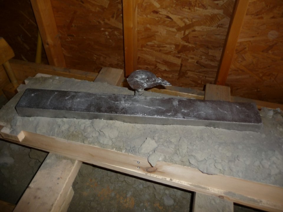
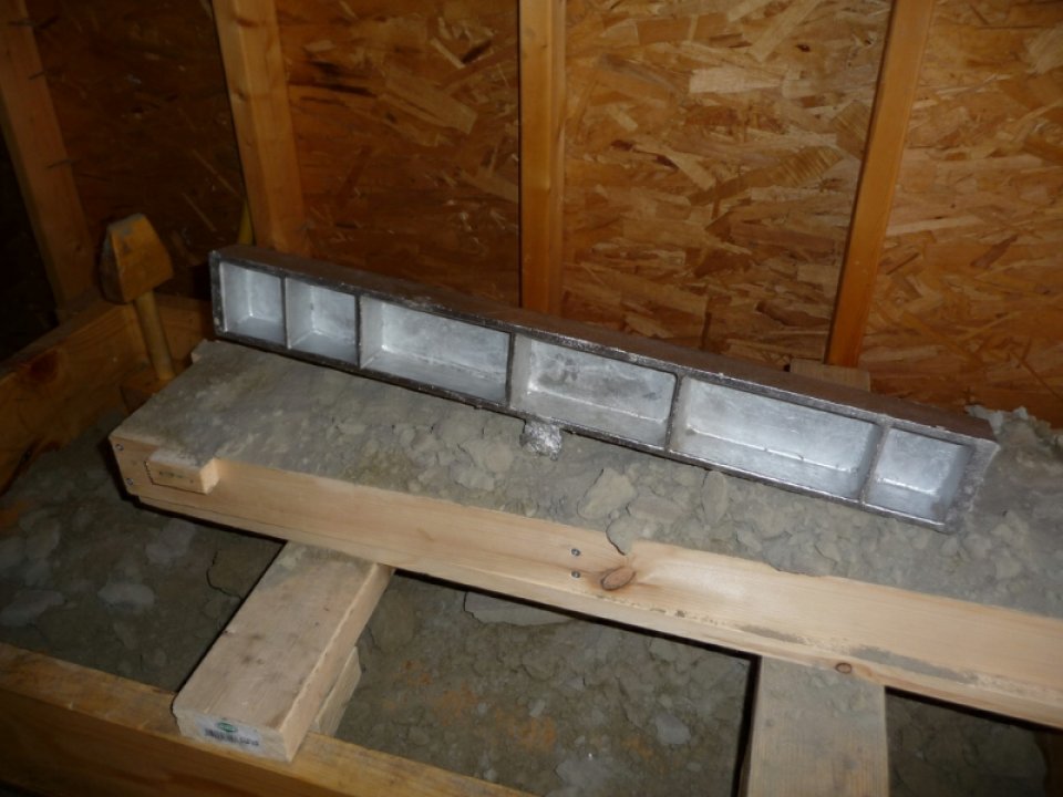
After probably 30min to an hour, it was time to open up the flask and see what I got. It was an awesome feeling opening the flask up and seeing a just about perfect ( according to my standards ) casting.
Photos of the bed casting:
Video Of Both Attempts At Casting The Bed »
It was time to make the bed feet patterns. The original design in book #2 suggests making one pattern for both the headstock and tailstock ends, however from what I was reading it sounded like the headstock needed more support. I increased the headstock end footing to match the length of the headstock, and also increased the wall thicknesses of both headstock and tailstock feet. Casting these patterns was much easier than the bed casting due to both size and amount of metal required.
Photos of the headstock foot pattern, mold, casting:
Photos of the tailstock foot casting:

Video of me pouring the tailstock »
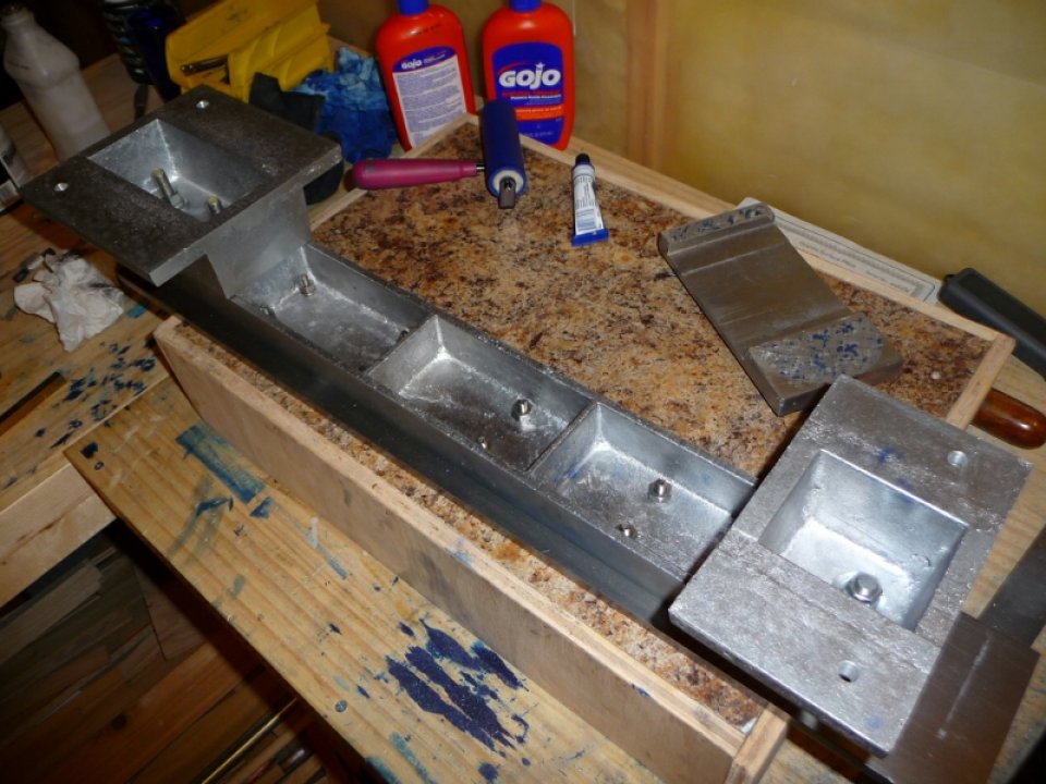
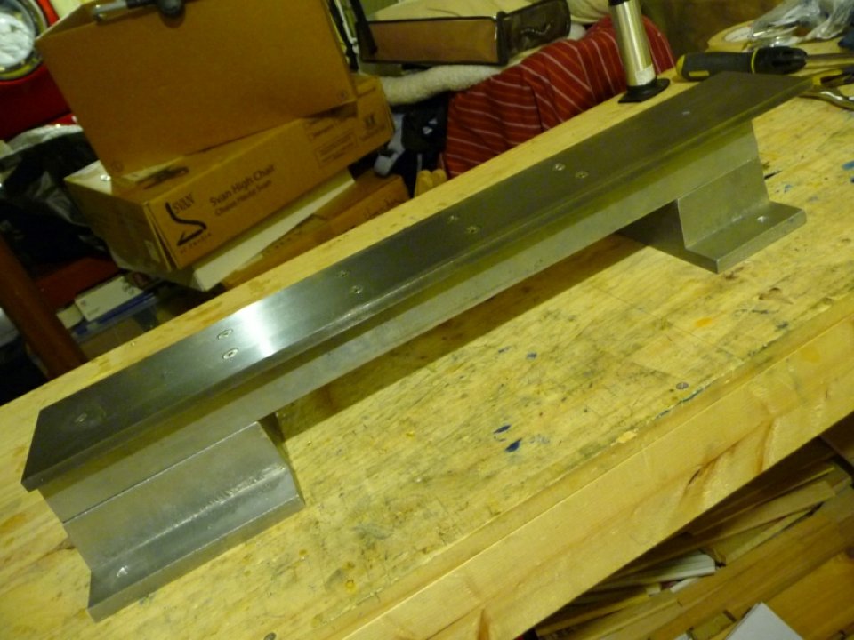
Now that I had the bed and feet castings, I proceeded to clean them up. I use a hacksaw to cut off the sprue, and then used a mill file to remove any flash from the parting line.
Photos of the bed with feet cleaned up:

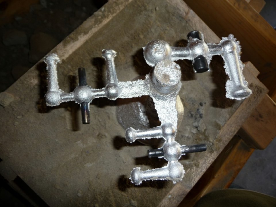
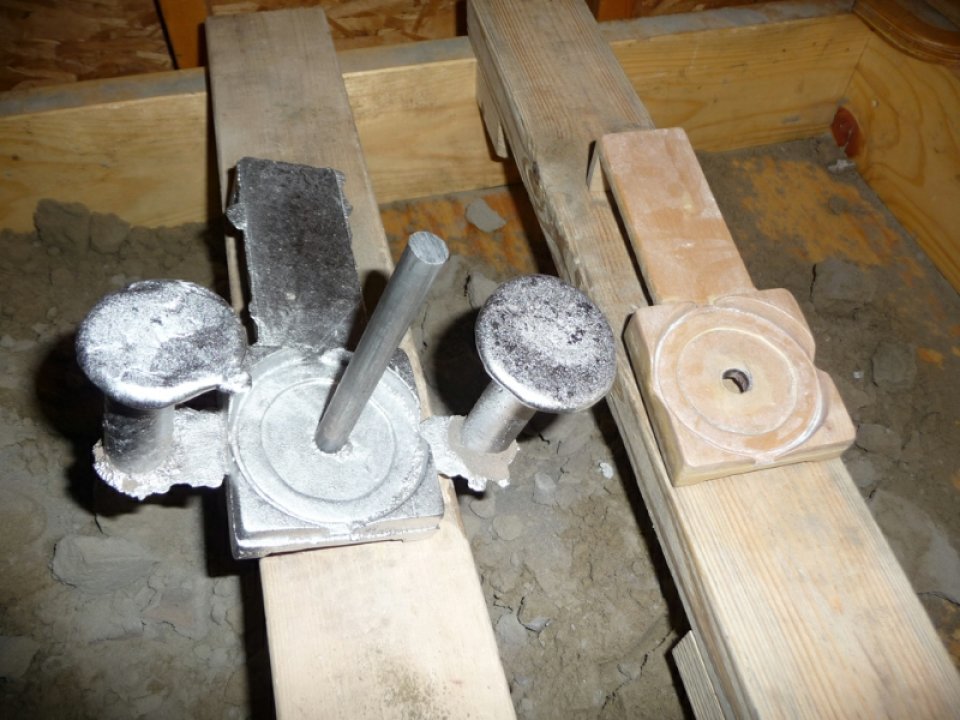
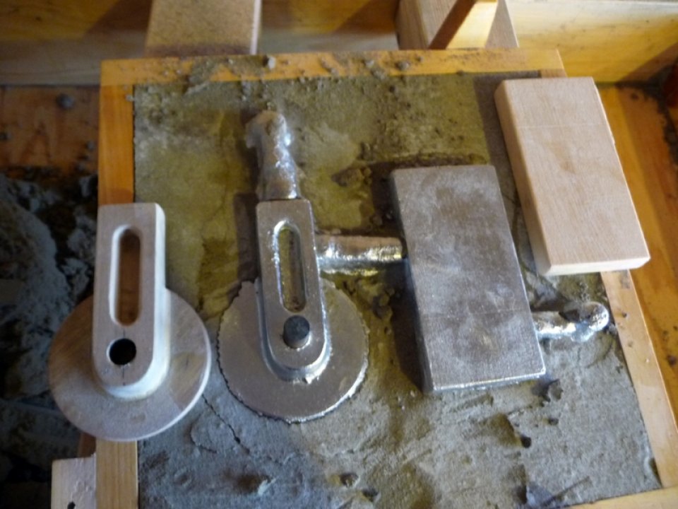
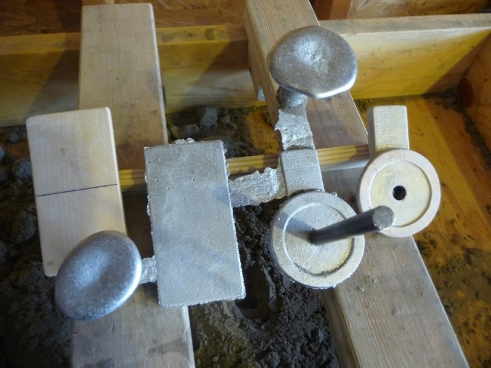
The lathe requires a few handles, and I decided it was a good time to try and get those out of the way. I used the same sizes as book #2 describes – a 3″ ball crank for the leadscrew, 2″ ball crank for the carriage and cross slide, and 1″ for the compound. With my 12×12 flask I can easily cast 3 cranks at a time, and that was what I did.
Photos of casting ball crank patterns, mold, castings:

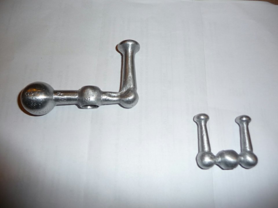
They turned out pretty good, and clean up really well. The main problem with aluminum cranks like these is that they get your hands really dirty. I’ve been trying to figure out ways of coating the cranks but nothing has held up. I know you can annodize aluminum, but I don’t really feel like getting into that at home just yet.
Photo of some of the ball cranks cleaned up:
At this point I was ready to prep the bed casting for the ways. The bed needs to provide a good / flat surface that will support the ways. In order to do that without a milling machine, one has to learn how to scrape the part by hand. To me this seemed to be quite the daunting task, as there wasn’t too much information online about the technique, and the book is rather vague. The Gingery Yahoo Group was of some help, but it is a process that is probably best learned with the help of an instructor or mentor.
So what is hand scraping? Well you need a reference surface that is really really flat. I believe you can make your own reference by hand scraping 3 surfaces with respect to each other, but I have never tried that. Anyways, I took the easy way out with that regard and purchased a granite surface plate from enco on sale with really cheap shipping. The plate I purchased was Grade B and flat to within .0002 of an inch, which was more than I needed for this lathe. I also ordered some machinist hand scrapers and dykem blue.
Photo of hand scraping tools:
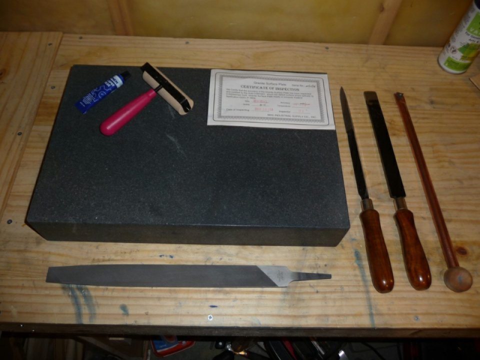
What is involved in hand scraping? First and foremost you need to be able to grind the scraping tool such that it will do a good job at scraping. I’m not going to get into details on this, though there is some good information online and in the Gingery Yahoo Group files on this ( there is also a hand scraping yahoo group ). Once you have a scraper that will scrape – takes small shavings of metal off with each pass, you proceed to use an ink roller to roll out a thin layer of dykem blue on the surface plate. You then take the part to be scraped and place the surface to be scraped face down on the thin layer of ink. You then carefully rub the part back and forth a little bit to transfer the ink from the plate to the high spots on the surface to be scraped. Carefully lift the part off the plate and then proceed to scrape the high spots ( those marked in blue die ) at a 45deg angle ( not 45deg angle in terms of how you hold the tool, moreso in terms of how you come at the high spots ). Anyways, scraping itself is a learned technique that requires lots of practice. It took me quite a while to get the feel for it and to be able to shave off small bits of metal. I will work the high spots at the 45deg angle in rows coming back toward myself such that I’m not covering the remaining high spots, that are still blue, with with the metal shavings. Once I have all the bluing scraped, I’ll wipe the surface clean with a rag, and proceed to run a very fine sharpening stone over the scraped surface in order to remove any burrs that would adversely effect the next marking on the surface plate. After the stone I’ll wipe the surface clean again, and then will make sure the ink is still good on the plate – the roller tends to get loaded so without using additional ink you can roll on the plate again to redistribute the remaining ink to a consistent thin layer ( add more ink as need be ). You then mark the surface again in a similar fashion, and then proceed to remove the marked high spots again but this time at the opposing 45deg angle from the last pass. This effectively has you coming at it this way first / and then this way next and then back to this way /. You are effectively cutting a cross hatch pattern after two passes. When I first start scraping a surface I’ll be fairly aggressive until the whole surface has some high spots. Once that happens I’ll lighten up. The gauge of flatness is how many spots per inch there are, and obviously the whole surface should be covered in spots.
My first efforts with scraping were done on the bed casting. It took me roughly 5 months on and off to get the hang of it. Realistically I started working on it, and found I wasn’t getting where I wanted to be. I ended up taking a few months off and then had a new burst of motivation that got me back to the project. I don’t know if it was shear luck, but it finally started to feel right for me, and I ended up getting the results I wanted.
Photos of high spots on the bed casting – 11/04/2009:
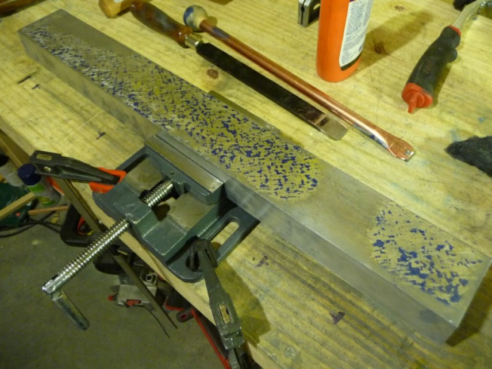
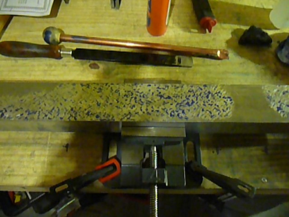
Photo of high spots on the bed casting – 4/12/2010:
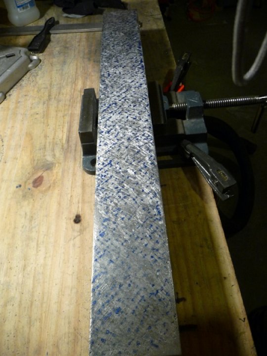
After scraping the bed casting to the point where I believed it was ready, it was time to hand scrape the back ways. It was a bit tricky scraping this surface as it was only 3/8″ thick, however the smaller surface area made the job go by a lot faster.
Once the back way was scraped, it was time to mount the ways to the bed casting. In book #2, Dave recommends 4 channels in the bed casting that are used to mount the ways and feet, however from what I was reading it didn’t sound like it was the most rigid setup. I decided that I would instead bolt the ways to the bed with two rows of machine screws equally spaced over the length of the bed. I also decided to mount the headstock end foot with two bolts, and the tailstock end foot with just one as usual. I used a drill press and jig to accurately drill the holes in the way plate. The machine screws were to be 1/4″ – 20, and the foot bolts would be 3/8″ – 16 to the book’s spec. I did not initially drill the 1/4″ holes to their full 1/4″ diameter, instead I drilled the holes for a 1/4″ – 20 tap. The plan was to use the drilled ways as a template for drilling the bed casting. I clamped the centered ways to the bed casting and proceeded to use a hand drill to drill the holes into the bed casting using the ways as the template. Once done I removed the clamps, and enlarged the ways holes to 1/4″ and counter sunk for the machine screw head such that the screws would be slightly recessed. I then tapped the bed casting for the 1/4″ – 20 machine screws.
Photo of the bed & ways scraped with holes drilled:
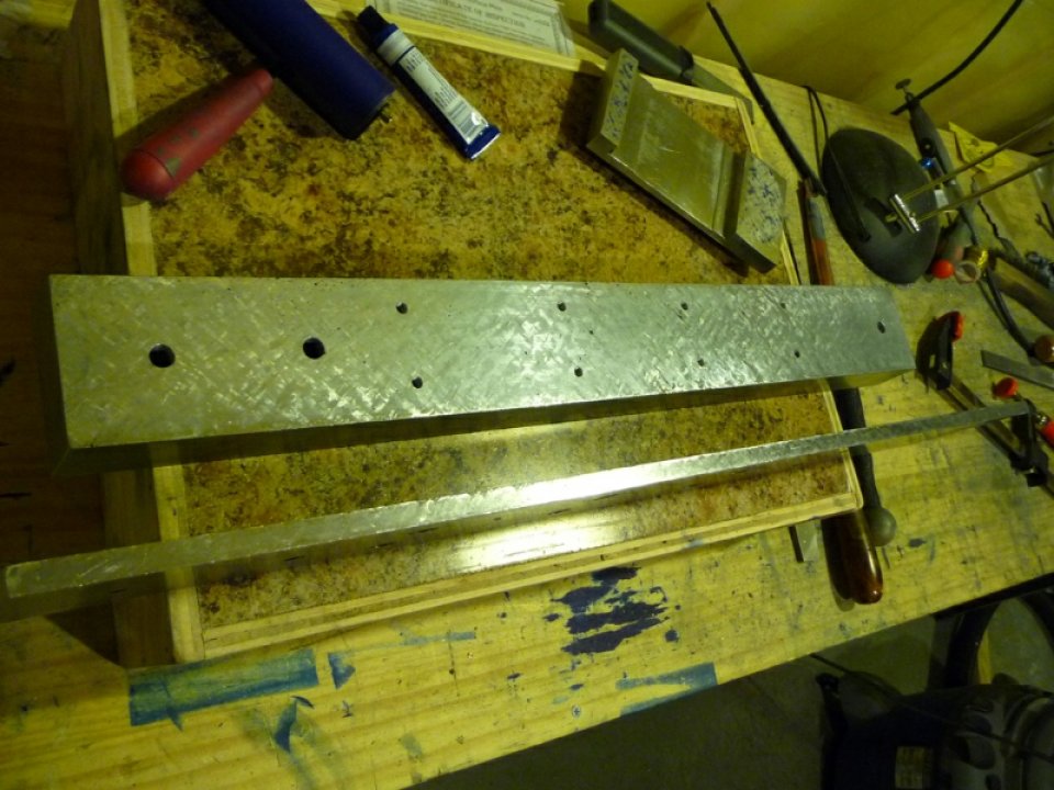
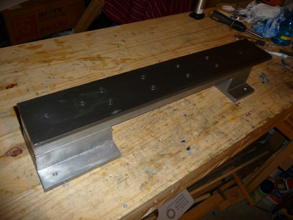
Photo of the ways mounted to the bed mounted to the feet:
With the bed completed, it was time to work on the carriage. The carriage will run along the ways and provide a base for the cross slide and apron. This lathe is designed with box slides ( don’t have the tools to cut anything fancy like dovetail slides ).
Photos of the carriage pattern and casting:
The idea of the box slide on the lathe is to provide the smoothest movement across the ways while maintaining a tight fit. The setup has to be adjustable as the metal will wear down over time from friction. The casting provides the top and sides of the box, while clamps provide the bottom. The clamps are fitted with shims such that a tight yet smooth fit can be made on the ways ( shims can later be removed to adjust for wear ). A square gib is used to provide the adjustable contact with the back ways. To adjust the gib set screws are installed on the casting ( via drilling and tapping the appropriate holes ). Locking nuts on the set screws provides the ability to set and lock the gib setting once adjusted for a smooth yet tight fit.
All of the box slide patterns have wear pads built in. The pads are first separated with a hacksaw such that there are two top pads, and two side pads. All wear pads and clamp surfaces are then filed and hand scraped. The clamp surfaces are tested against the granite surface plate, and the wear pads are tested on the way plate itself. Since only the back ways was hand scraped so far, it is used as the test surface for the front and back wear pads. Once both pads are scraped to satisfaction, the gib is installed and the carriage itself is used as a test surface in order to hand scrape the front ways.
Photo of high spots on clamp surfaces ( just starting here ):
Once the carriage box slide is all set, the carriage is fitted with it’s own smaller ways such that a cross slide will slide along it perpendicular to the bed ways. The carriage casting has a channel at the top, which accommodates a feed screw such that you can attach a ball crank to the feed screw and drive the cross slide in and out ( sorry for the very basic and incomplete description of that ).
With the carriage completed, it was time to work on the cross slide. The pattern was fairly typical, though a 1/2″ steel shaft is used, as a core in the mold, to create a bore for the swivel base. Aluminum will not bond with steel, and if properly waxed it is fairly easy to remove a steel shaft from an aluminum casting. This very fact makes it possible to create fairly accurate bores up to a certain size without having to create sand cores.
Photos of the cross slide pattern and casting:
The casting was cleaned up, steel shaft removed, and it’s box slide done in a similar fashion to that of the carriage. It was a bit tricky to locate the center of the feed screw channel on the cross slide from the carriage, but once done the a hole was drilled through both castings. The hole was initially drilled for 1/4-20 tap, and then the cross slide hole enlarged to 1/4″. The carriage hole was then tapped for 1/4-20.
The cross slide feed screw is made out of 1/4″ steel round stock, and a good length of it is hand tapped with a die to 1/4″-20. The feed screw is run through the cross slide, then through a setscrew collar, and then threaded into the carriage feed screw channel. A setscrew collar and 2″ ball crank are installed on the end of the feed screw.
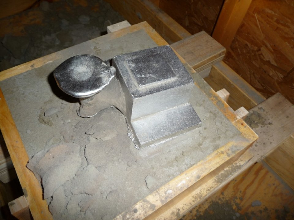
With the cross slide done, it was time to work on the swivel base. The swivel base is cast on an arbor that fits into the 1/2″ bore in the cross slide. This provides a means of setting the compound & cutting tool at an angle.
Photos of the swivel base and apron pattern, casting:
I ended up casting the ‘apron’ in the same flask with the swivel base. The apron is connected to the carriage and provides a mounting surface for a split nut which allows the leadscrew to drive the carriage along the ways.
The swivel base pattern was cleaned up, and fitted with a small way plate for the compound. Small clamps where made for the cross slide such that the swivel base could be locked at the selected angle.
With the swivel base completed, it was time to work on the compound. The compound is like the cross slide in that it has a feed screw, however the top of the compound will have the toolholder. The compound also has a box slide which provides a means for advancing the cutter into the workpiece.
Photos of the compound pattern + casting:

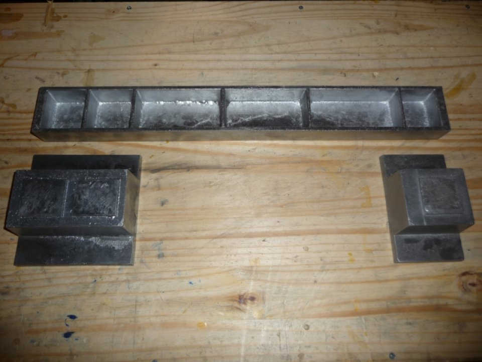
I ended up casting the leadscrew bearings with the compound. The bearings will hold the leadscrew in place while it is turned by a 3″ ball crank. The bearings are mounted on the far left and right of the bed casting.
The compound was cleaned up, and it’s box slide done in a similar fashion to the carriage / cross slide. A feed screw for the compound was setup in a similar fashion to the cross slide feed screw ( the swivel base has a feed screw channel ). A 1″ ball crank was used for the compound feed screw.
Two 3/8″-16 holes were tapped on the top of the compound to accommodate a homebrew toolholder from a lawnmower axle bolt. A 1/4″ square channel is cut and filed from the bold to accommodate 1/4″ square lathe cutting tools, and a setscrew is setup on the top of the toolholder to lock the tool in place. The toolholder was installed on the compound.
With the compound done, it was time to get the leadscrew working. A split nut was created as described in book #2. The apron was modified to hold the split nut, and a lock / release mechanism setup with a lever in order to engage / disengage the carriage on the leadscrew. The apron was mounted to the carriage, and the leadscrew bearings mounted to the bed. The leadscrew was made from 3/8-16 threaded rod, bearing journals made from pipe nipples, and a 3″ ball crank. The leadscrew journals were turned down on my drill press, and threaded half way to fit on the ends of the threaded rod ( though book #2 shows how to do it without a drill press ). Locking nuts were used to lock the journals onto the threaded rod, and a 3″ ball crank was fitted onto the leadscrew.
Photo of progress at this point:
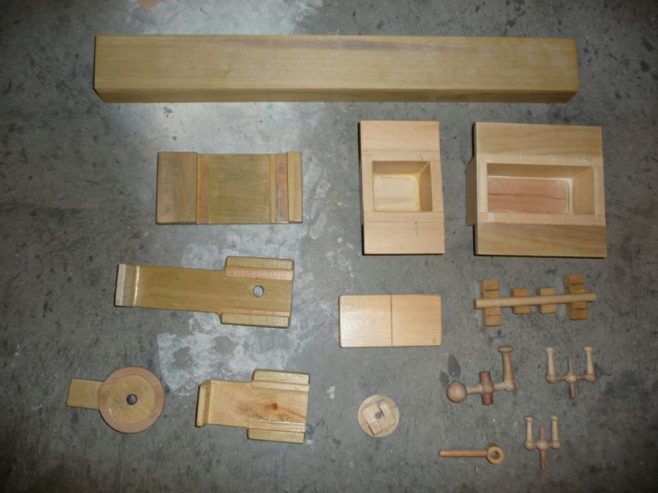
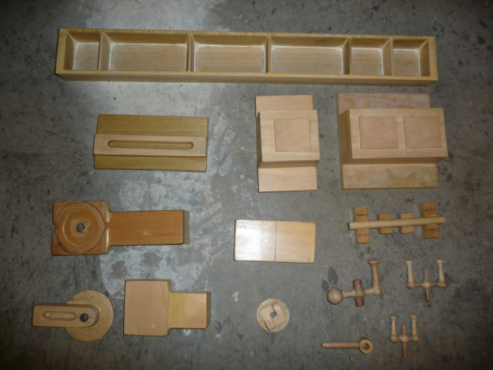
Photos of the wood patterns made for the lathe up to this point:
At this point it was time to start working on the motor mount, motor controller, and headstock.
The original Gingery Lathe calls for a counter shaft with pulleys of varying sizes. Belt changes were to be used in order to achieve different speeds. This seemed a bit tedious to me, and it really sounded like a great opportunity to work on some electronics for the lathe. It was my goal to build a controller and driver for a 2hp DC treadmill motor that I had recently acquired.
Photo of DC Treadmill Motor:
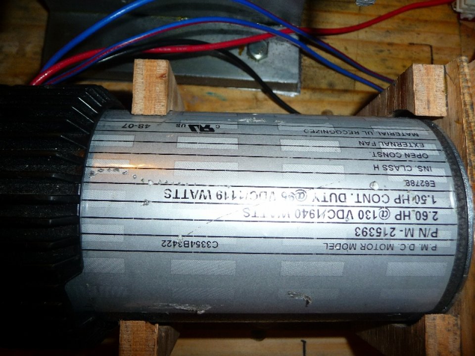
Photo of initial test setup for the motor ( 555 timer @ 7khz, 10% duty to Power Mosfet driving Motor with rectified 120VAC ):
*obviously not the best setup, however I wanted to see the motor turning before building a more involved controller / driver for it.
Video Of Progress Thus Far & Motor Test Circuit Driving The Motor »
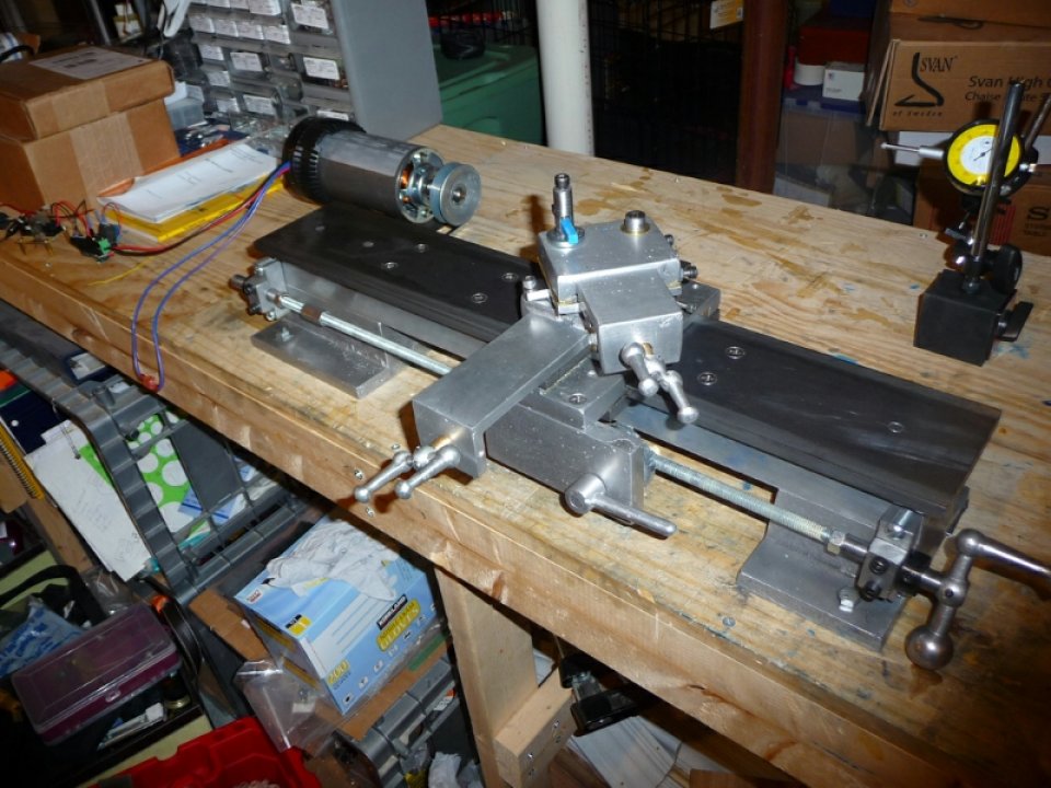
For the lathe to be accurate, the spindle must run as parallel to the bed ways as possible. Without a lathe to make an accurate bore in the headstock casting, the lathe up to this point is used instead to do the job. A temporary headstock made from pillow block bearings and angle iron was setup in order to provide a holder for a temporary boring bar. A jig was created based on the location of a 3/4″ bore in the headstock casting. The jig is used to accurately adjust the temporary headstock to the proper position for the boring operation. The idea is to setup the headstock casting with a box slide, and to connect it to the leadscrew with a temporary apron. The headstock is then driven onto the boring bar in order to increase the 3/4″ bore to fit the appropriate bearings.
With the temporary headstock done, the temporary spindle / boring bar was created and a 4″ pulley added to the outboard end. A motor mount was then fashioned for the treadmill motor, and a 2″ pulley installed on the motor shaft. A V-Belt was used to drive the spindle from the motor shaft.
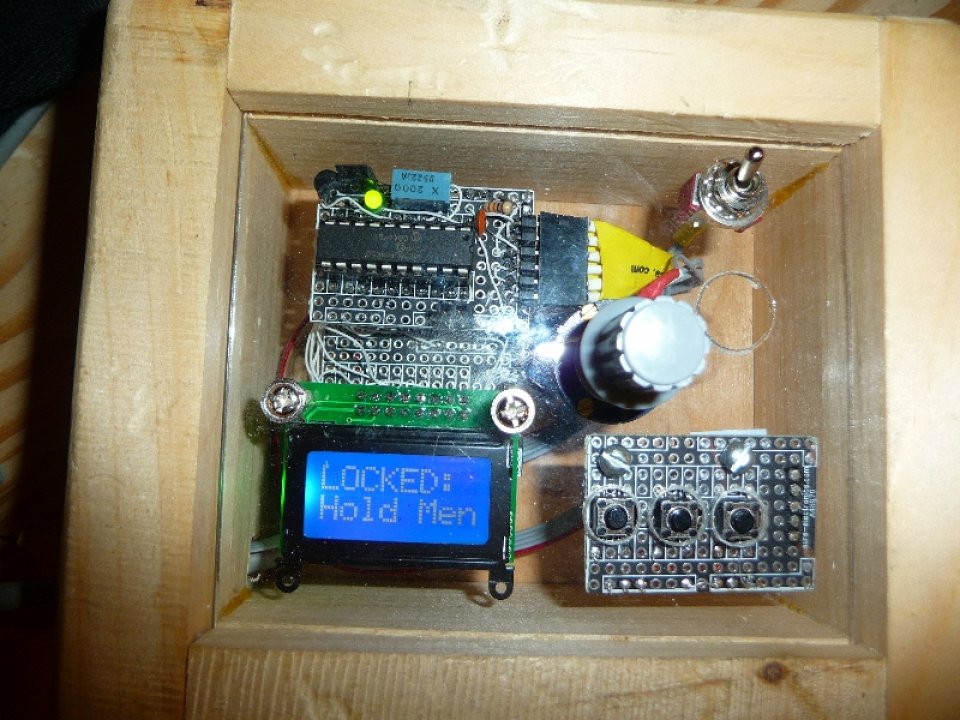
At this point I was ready to start working on the real DC Motor Controller. I had a few PIC18LF14k50 microprocessors lying around which are quite capable and feature rich. I decided to use one of these for my controller. I designed the controller and driver to be completely separate, and powered by isolated power supplies. To keep the controller isolated from the driver, an optocouple was used to transmit the PWM signal. The controller is housed in a small box, with knob and 3 buttons for controls. The controller’s firmware provides a comprehensive interface for setting RPM, PID control constants, min / max settings, etc… The PIC18LF14k50 has USB capability, but I haven’t needed to hook it up to a computer yet ( maybe future versions of the controller will have support for USB ).
Photo of the controller box:
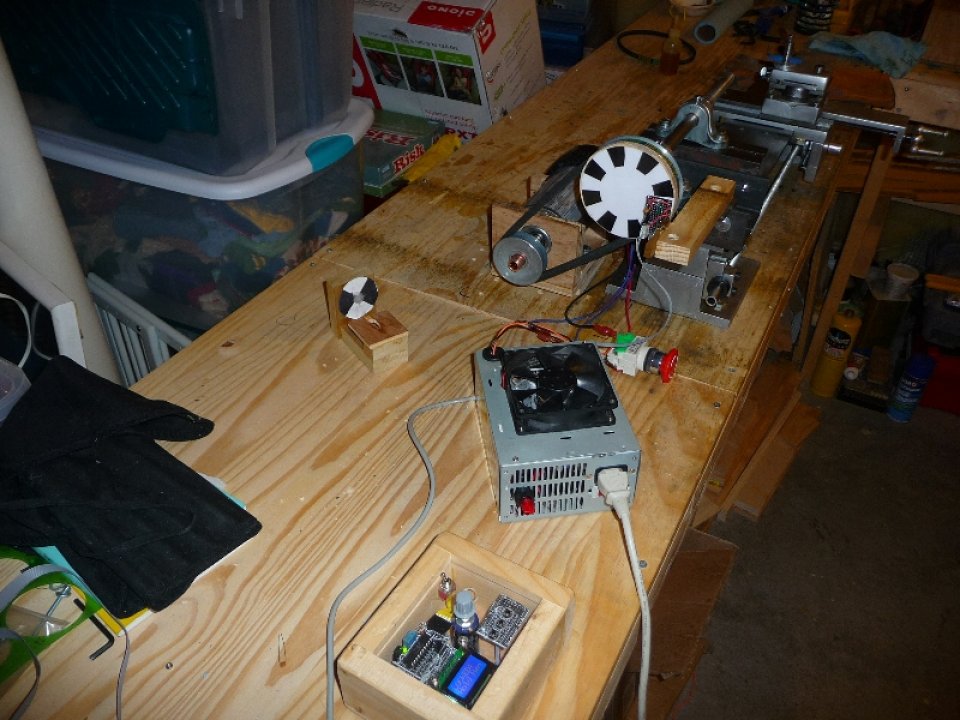
A separate board which mounts to the headstock was created to provide RPM data to the controller ( required to display current spindle RPM and for the closed loop PID control algorithm ). An encoder wheel is mounted to the outboard side of the spindle pulley, and a special mount was created such that the optical detector ( QRD1114 ) would be facing the encoder wheel. The controller counts each transition from white to black, or visa versa, maintaining a count for a given period of time. Interrupts are used at known intervals in order to calculate the current spindle RPM.
The motor driver is a fairly simple design. I decided not to use an h-bridge for this initial driver, and instead would drive the motor with a single power mosfet. Reverse is provided via a separate relay connected to a switch mounted to the driver’s case. If I ever decided to convert this to a CNC lathe, or even setup something like an electronic leadscrew, I would most likely need to be able to reverse the spindle in software, at which point I would need to either drive the relay from the controller, or build an h-bridge version. The driver is housed in a gutted ATX power supply case. These cases make great project enclosures, and for this project the large power supply fan and heatsink was ideal. I was able to pickup quite a few ATX power supplies for $5 locally, what a deal.
Photo of Controller, Driver, Motor Temporary Headstock + Spindle Ready To Test:
Video of me testing the Speed Controller / Driver / Temporary Headstock »
The controller / driver has worked out so far though I still have quite a bit of tweaking in software to do. This ends the recap, my next post will be with regard to casting the Headstock and fitting it to the bed ways. I’ll finally be able to use the lathe to boring the headstock soon.
Cheers,
Morgan
Where can I get more info about your controller? I am building a Gingery style lathe myself, and would LOVE to build a controller like yours for it!
I’m working on putting all the files together now, hopefully soon I’ll have everything available online for download.
Cheers,
Morgan
Nice writeup on scraping!
good day
You could not give me a bi drawings of your lathe?
thanks
Hey Alexandr,
Sorry I have no drawings, but if you look up ‘Dave Gingery Lathe Book #2′ you’ll find all the information you need to build the lathe. I increased the size of the design a bit, but it is basically a gingery lathe.
Cheers,
Morgan
Whats again Morgan. I was curious if you tapered the ribs? on the wooden pattern because when I ever I see the cast the taper is not visible.
the ribs go straight across, no diagonals, but they do need to be tapered slightly to provide enough draft in order to be able to successfully remove the pattern from the sand mold.
Cheers,
Morgan