 There are quite a few skeptics as to the benefits of Colloidal Silver, I for one can neither promote nor discount the benefit of it’s use as I have very little experience with it myself. My Mother In-Law showed an interest in producing colloidal silver at home which seemed like the perfect opportunity for me to help her out, and also to produce a device that potentially could help many others attain a high end generator for home production at a low cost in comparison to other commercial generators available on the market today.
If you are interested in building this project yourself, be sure to download the project files on the ‘Project Page’ link below. Also, I have put together an accompanying video which goes through the build as well. There also may be a ‘Makerspace’ in your area that could help you with the build if you are not familar with producing etched circuit boards at home, soldering, etc…
Project Page:
SilverMAX Colloidal Silver Generator Project
Video:
The Making Of The SilverMAX Colloidal Silver Generator
The first order of business is to take a look at the ‘Parts List’ excel spreadsheet in the project download. Once you have acquired all the required components it is time to get started on the build.
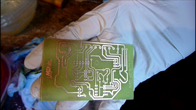
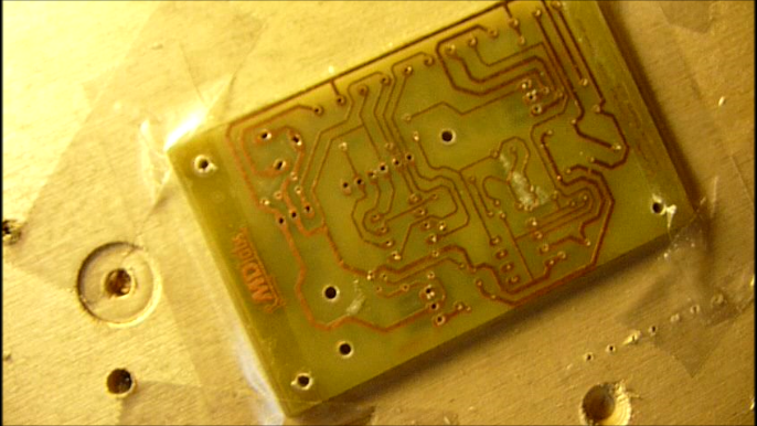
Step 1: Etching The Circuit Boards
There are two boards in this project which can either be on the same board, or broken up into two separate boards. The interface component works nicely as a separate board as it’s layout can be used as a template for the mounting holes in the enclosure. The other benefit being that the board is mounted to the enclosure using the panel mount toggle switches.
To produce circuit boards at home I use the toner transfer method. In the past I have used a Glossy Photo paper, however I have found simple ( and cheap ) Magazine Paper is the most effective medium for transferring the toner to the copper clad board. I have a fairly old Samsung ML-1740 laser printer that I use which works well enough. When feeding the Magazine Paper into the printer it is much easier if you place it on top of a standard sheet of plain printer paper.
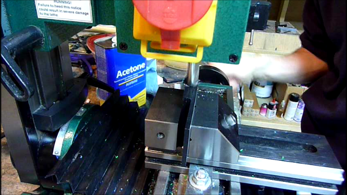
Prepare the circuit boards by cutting them to size, cleaning with a scotchbrite pad, and then with Acetone. Be sure to wear some type of rubber gloves, as the oils from your fingers will most likely ruin the transfer. When the boards are prepared, cut the printed circuits to size, place over the copper board and tape. I have found, at least with my laminator, that at least on the first two passes the paper can move ( possibly not the case with a more expensive laminator ). I have one of those cheap $19 purple cow laminators from Costco, which works fine, but I have to run the boards through 7-10 times to get a good transfer. Place the boards into water ( or run under the faucet ) in order to remove the Magazine Paper. I have found that it is extremely easy to remove the paper, and the traces turn out perfect almost every time.
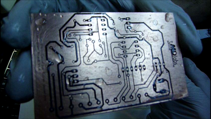
With the toner transferred to the boards, prepare a small sponge that you will use with a small amount of Ferric Chloride to etch the boards ( if you use something else by all means go for it ). You can attain the needed chemicals from your local RadioShack. I like to work over a disposable rubbermaid container, and be sure to wear rubber gloves. Saturate a small sponge with a small amount of Ferric Chloride. Gently rub the sponge back and forth over the board, and within about 5 minutes the board should be etched. Rinse the finished boards off with water, and then clean the remaining toner off with Acetone.

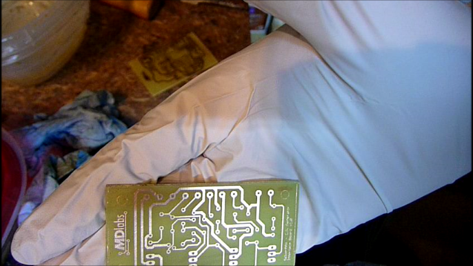
You can now optionally add the silkscreen layer to the boards if you like. You would simply print out a mirror image from the eagle file ( or use the pdf which is already mirrored ). You transfer the toner to the fiberglass and remove the Magazine Paper under water.
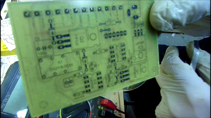
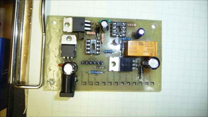
Step 2: Drill & Populate the Boards with the Components
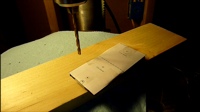
I don’t have anything too fancy for drilling the boards, though taping them down to a piece of junk 1/8″ plywood is helpful. I use tungsten carbide micro drills that I got dirt cheap off of ebay in my floor model drill press, though any drill press will do.
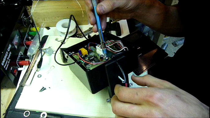
Photos definitely do this step more justice than words, but basically solder all the components on the boards that you just made.

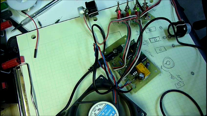
Step 3: Test the Electronics
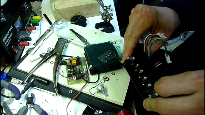
You will need to create a few cables that run from the interface board to the 10k Panel Mount Potentiometers, and also two cables from the 4 conductor intercom wire. The controller should have two 1×4 Molex KK 2.54mm friction lock headers which these two cables will connect to. One end of the cables are soldered directly to the interface board, while the other end is setup with the Male Molex 1×4 KK crimp housings. If you want you can solder the cables directly to the Controller and not bother with the Molex cables, however it could be a pain to work with.
You will also make two more cables from 2 conductor telephone cable ( or speaker wire ). One of the cables is used for the electrodes, and the other for the connection between the interface board and the laser module. Do not solder the alligator clips onto the electrode wires at this time, but you can strip the ends down such that you can test the voltage with a multimeter when you turn the device on ( same goes for the laser +/- cable ).
Using a PICKit2 ( or 3 ) and the 1×6 PICKIT header on the Controller you can now program the PIC12F510 using the ‘SilverMAX.hex’ file found in the ‘Software’ directory of the download for the project.
To test the generator at this stage you will want to use the 12VDC wall wart and plug it in. Mess with the switches a bit to ensure that all the indicator lights are working as expected. Then you can proceed to test the variable speed fan control, by switching the Magnetic Stirrer Enable switch on, the Run / Standby switch on, and the Power switch on. You can then adjust the Magnetic Stirrer’s speed knob watching for a change in speed of the fan. Next you will want to test the output leads for the Laser – you should see a +5V there with a multimeter. You can now proceed to test the electrode output – you should see +12V or -12V. Every minute or so you should also hear a clicking sound from the relay on board, and should also notice the polarity of the electrode leads switching automatically.
Step 4: The Magnetic Stirrer
The Magnetic Stirrer in this generator is basically a 12VDC power supply fan with 2 rare earth magnets epoxied to the center of the moving part of the fan. You do need to be careful when placing the magnets, as orientation matters. If done incorrectly you will find the stir bar rotating on the outside of the flask, versus spinning in the middle ( watch the video for a visual of this ).
Test the hold of the magnets on the stir bar, by placing the stir bar in your flask and holding it over the magnets. Ensure that the bar locks in the center of the flask and spins appropriately when you turn the fan by hand.
Place the magnets on the fan, ensure the orientation is correct, and then prepare the 5 minute epoxy according to the directions on the package. Glue the magnets down to the moving part of the fan ( they should stick to the magnet in the fan, and be on the outer edge ). As the epoxy sets up move the magnets in a bit closer to the center without having them touch ( can be a bit tricky ).
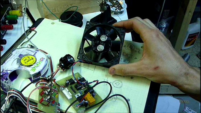
Once the epoxy has set, I attached a screen of sorts to the back of the fan in order to protect the electronics / cables. I used a cut piece of scotchbrite pad and zip ties for this – the scotchbrite came in a 12×12 sheet and was porous enough for air to flow through it.
Step 5: Prepare the Enclosure
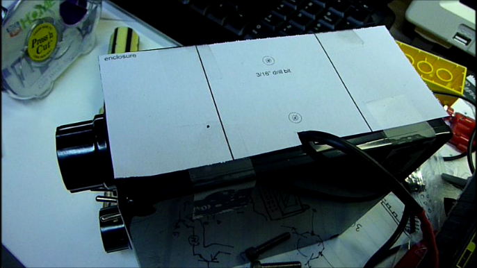
The project download includes all the required templates to modify a 120mm square project enclosure to house this project. Using the first ‘fan mount’ print out you can accurately locate the 4 mounting holes for the fan at the center of the enclosure ( if the fan is 80mm square that is ).
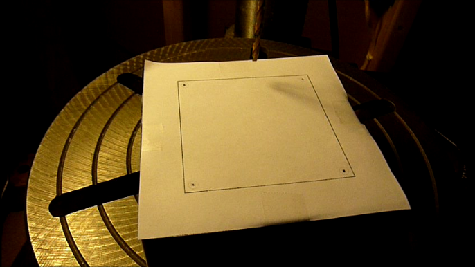
Once the fan mounting holes are drilled, prepare the mounting posts. I used 8-32 x 1″ machine screws with 2 washers and 1 nut as a spacer between the enclosure and the fan body to provide enough clearance for the magnets.
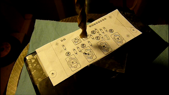
Using the ‘silver_generator_v1_interface_template.pdf’ print out the template for the interface board’s mounting holes. Tape the template to the face of the enclosure and drill accordingly. I find using a center punch to mark the holes first is extremely helpful at drilling these holes accurately.
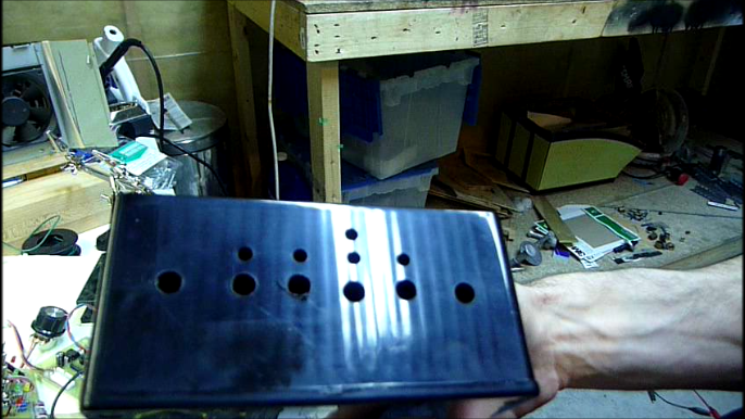
Locate two holes in the back of the enclosure, one for the electrode cable and one for the panel mount DC jack. Locate another hole on the right side of the enclosure for the laser light cable. Drill these holes out.
With the interface holes drilled, fit the two 10k panel mount potentiometers and lock in place with their locking nuts. Carefully place the interface board in the enclosure, and line up the switches and leds with the drilled out holes. Push into place and lock down the interface board using the panel mount switch nuts.
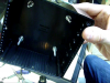
It’s now time to put the fan back into the enclosure on the mounting posts and then lock it into place using 4 additional nuts. It is a bit tight space wise, but I was able to get it done with a little effort.
Next you will want to place the controller board on the Fan’s screen, and then mount the DC jack to the case via the hole that was drilled out for it. Also, run the electrode cable through the hole in the back of the enclosure, and the laser cable through the hole that you drilled in the side of the enclosure.
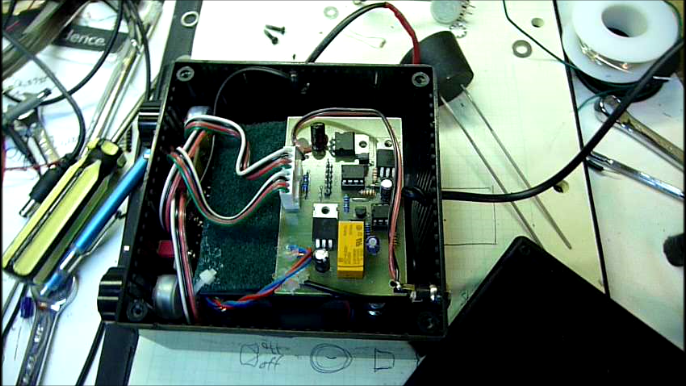
You can close the enclosure for now.
Step 6: Additional Preparations
You will now need to solder the alligator clips to the two conductors used in the electrodes cable. You should also solder the laser module to the two conductors used in the laser cable. A bit of heatshrink tubing will protect the soldered portion of the laser’s cable. The insulation on the alligator clips should cover, and protect the solder joints at the electrodes.
You will need to take the #7 rubber stopper for the Flask, and drill two holes, about 3/4″ apart, that will fit the two 14 gauge 99.99% pure silver wires snugly. The wires I used were 5″, however I would recommend using 6″ wires with the 500ml flask. Push the two silver wires carefully into the stopper, ensuring that they are parallel to each other.
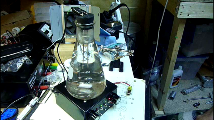
Step 7: Testing the Colloidal Silver Generator
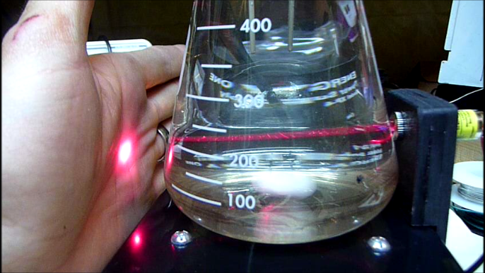
You should now have a 100% functional Colloidal Silver Generator at this point minus the laser mount. To test everything out place the stirbar in the flask, and fill to the top with distilled water ( leaving space for the rubber stopper of course ). Place the rubber stopper with electrodes on the flask, and then position the flask on the generator. Hook up the two electrodes via the alligator clips ( polarity does not matter ).
At this point you are ready to test things out. I would recommend looking at the ‘Instructions.doc’ file in the ‘Documents’ folder of the project download file on the projects page.
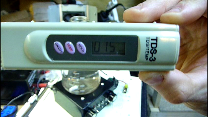
Some simple tests to start, would be to ensure that the magnetic stirrer is working as expected – turn the power on, run / standby to on, stirrer enable to on, and then adjust the speed with the left adjustment knob. You should also try the laser on / off switch ensuring that the laser is working as expected. I would recommend at this point letting the generator run for 5 hours with the right knob set at the middle position. You should purchase a TDS meter to determine the ppm of silver produced after that time period – my first prototype device produced 15ppm of colloidal silver in 5hrs.
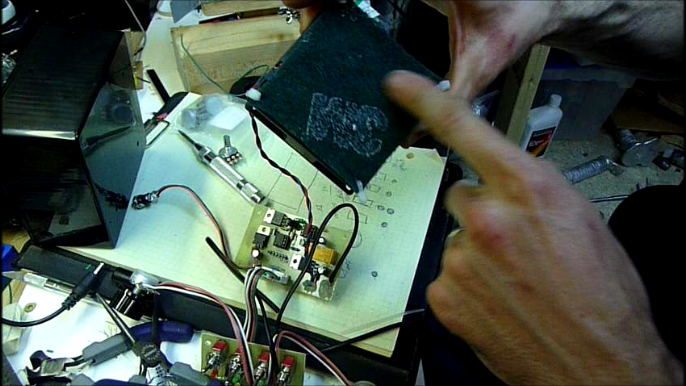
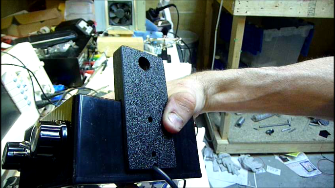
Step 8: Laser Mount
I built the laser mount from 3 layers of 1/8″ ABS plastic sheet glued together with pvc cement. You can get an idea of how it looks from the video / photos, and also from the template file included in the project files.


—
That just about covers the build of the SilverMAX Colloidal Silver Generator. If you have any questions feel free to leave a comment and I’ll be sure to get back to you as soon as I can. If you have an interest in purchasing a kit, or boards, let me know – at this point I’m not planning on selling kits, but if there is substantial interest it may be something that I will do in the future.
Cheers,
Morgan
what current is use 1mA ??? or more? for silver electrode?
Hey Burlacu,
The current on the SilverMAX generator is not 100% fixed, you can set the desired current ( production level ) via one of the adjustment knobs. The generator has a buck converter that maintains a constant current through the electrodes as the resistance of the solution goes down, which will produce more consistent results. As I’ve tested I don’t believe you’ll see anymore than 10mA running through the electrodes, and the current sense resistor value was selected to cap the upper limit on the current selection knob to ’10mA’.
Let me know if you have any other questions,
Cheers,
Morgan
Hello Morgan. ‘m Brazilian. Your driver can be used in an engine 90 V
20 DC?
Hey Celso,
For the DC Motor Controller / Driver project if the motor is 90V DC you can use it, though you may need to select a different mosfet if you have higher power requirements, though the driver in the project was used to drive a 2hp treadmill motor which was running at 160VDC @ 10A ( around 1.6kW )
If you have any questions let me know via comments here, I can always email you, etc… if you need any help with it.
Hi Morgan,
This looks great. Do you sell these? My mechanical skills is using a hammer and a screw driver.
Hi Morgan i like the look of this project have the tools and the skills to construct although not sure what the PICKit2 controller part is for.Have been making Colloidal Silver for a long time naw I average about 10/15 ppm clear low voltage + micro amp systems i think work best it may take longer but some things you cant rush what i would like to know is are you selling any kits maybe you could check out my shop on etsy (creativesilverworks) and we make a deal
Hi
Do you sell kits for this? I dont have tools to make this at home?
Currently I don’t sell kits, but I may put a few together that I will sell in the future as I have had a couple of inquiries about this so far. I’ll drop you an email when I have something available if you are interested.
Cheers,
Morgan
Interested in just the etched board (I have a drill press to finish it) If you ever decide to sell please let me know. Appreciate your time, Frank
hello morgan, i was wondering if and how this project could be modified to make colloidal gold ? please fell free to contact me back.
Hi Morgan, I seem to have left my comment somewhere else on your site. Sorry for the mistake, but just incase I totally lost it, I will again explain. I want very badly to build one of the SilverMAX generators from your design. I truly believe in the benefits of this design. I always go the homemade route vs buying mass produced. Both in quality of workmanship & parts!
My problem is my wife & I are both disabled & I just don’t have the hands anymore to do it. Are you able to make us one from your design? I will pay your price for it. We need this to help keep ourselves healthy for our grandkids. Thanks for your time & the effort it takes to do what your doing. Bobby O’Dell
Hey Bobby,
Glad you are interested in the SilverMax generator. At this point I don’t have any plans of building any additional units, however I do have a few ideas for some new designs in mind, that I would like to build at some point. Regardless, if I ever have the time I would love to build you a machine, though that being said we have a new baby due this year, and I probably won’t be able to get to it for quite a while unfortunately. Definitely keep me posted if your situation changes, and you end up buying a generator at some point in the future.
Cheers,
Morgan
Wondering if you have decided to sell kits yet?.
I do not have the skills necessary for this project , but I do like your design.
I have been looking for some time now for a generator that looks and performs as yours does.
thank you in advance.
This may be good for making some retirement money to put away.
Hi Morgan, first I’d like to say a big thanks for making your design available for anyone to build, its the best project I have seen for making colloidal silver.
I want to build it but can’t find the 12F510 here, just the 16F628 and I don’t have a programmer either, what I have is a Arduino Nano lying around, I’d like to use it instead of the PIC because maybe would be possible to interface with a LCD and add a couple of features. I have been using colloidal silver for years and find it pretty amazing, so I’d love to build my own generator.
I haven’t programmed PICs in years and I’m having trouble figuring out the initialization of the 12F510, TRIS bits and all that, I hope you don’t mind me trying to figure out how it works, and if you can explain briefly the program would be a lot of help.
This is a fun project that can also help cure diseases, great combination…